Breadboard
Unlike a perfboard or stripboard, breadboards do not require soldering or destruction of tracks and are hence reusable.
A variety of electronic systems may be prototyped by using breadboards, from small analog and digital circuits to complete central processing units (CPUs).
For example, US Patent 3,145,483,[2] was filed in 1961 and describes a wooden plate breadboard with mounted springs and other facilities.
In 1960, Orville Thompson of DeVry Technical Institute patented a solderless breadboard connecting rows of holes together with spring metal.
[4] In 1971, Ronald Portugal of E&L Instruments patented a similar concept with holes in 0.1 inches (2.54 mm) spacings, the same as DIP IC packages, which became the basis of the modern solderless breadboard that is commonly used today.
Integrated circuits (ICs) in dual in-line packages (DIPs) can be inserted to straddle the centerline of the block.
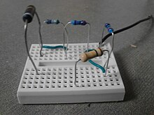
Interconnecting wires and the leads of discrete components (such as capacitors, resistors, and inductors) can be inserted into the remaining free holes to complete the circuit.
The layout of a typical solderless breadboard is made up from two types of areas, called strips.
In the middle of a terminal strip of a breadboard, one typically finds a notch running in parallel to the long side.
The casing contains additional equipment for breadboarding, such as a power supply, one or more signal generators, serial interfaces, LED display or LCD modules, and logic probes.
[21] For high-frequency development, a metal breadboard affords a desirable solderable ground plane, often an unetched piece of printed circuit board; integrated circuits are sometimes stuck upside down to the breadboard and soldered to directly, a technique sometimes called "dead bug" construction because of its appearance.
Examples of dead bug with ground plane construction are illustrated in a Linear Technologies application note.
[22] A common use in the system on a chip (SoC) era is to obtain an microcontroller (MCU) on a pre-assembled printed circuit board (PCB) which exposes an array of input/output (IO) pins in a header suitable to plug into a breadboard, and then to prototype a circuit which exploits one or more of the MCU's peripherals, such as general-purpose input/output (GPIO), UART/USART serial transceivers, analog-to-digital converter (ADC), digital-to-analog converter (DAC), pulse-width modulation (PWM; used in motor control), Serial Peripheral Interface (SPI), or I²C.
A single small SoC often provides most of these electrical interface options in a form factor barely larger than a large postage stamp, available in the American hobby market (and elsewhere) for a few dollars, allowing fairly sophisticated breadboard projects to be created at modest expense.
Due to relatively large parasitic capacitance compared to a properly laid out PCB (approx 2 pF between adjacent contact columns[23]), high inductance of some connections and a relatively high and not very reproducible contact resistance, solderless breadboards are limited to operation at relatively low frequencies, usually less than 10 MHz, depending on the nature of the circuit.
Solderless breadboards usually cannot accommodate surface-mount technology devices (SMD) or components with grid spacing other than 0.1 inches (2.54 mm).
Very complex circuits can become unmanageable on a solderless breadboard due to the large amount of wiring required.
At some point, very complex systems must be implemented in a more reliable interconnection technology, to have a likelihood of working over a usable time period.
However, prototyping techniques are still used for some applications such as RF circuits, or where software models of components are inexact or incomplete.