Cathode-ray tube
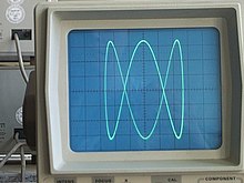
[2] The images may represent electrical waveforms on an oscilloscope, a frame of video on an analog television set (TV), digital raster graphics on a computer monitor, or other phenomena like radar targets.
In CRT TVs and computer monitors, the entire front area of the tube is scanned repeatedly and systematically in a fixed pattern called a raster.
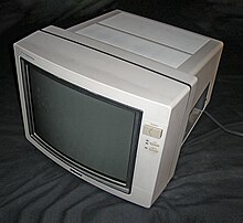
[80] Beginning in the late 1990s to the early 2000s, CRTs began to be replaced with LCDs, starting first with computer monitors smaller than 15 inches in size,[81] largely because of their lower bulk.
[82] Among the first manufacturers to stop CRT production was Hitachi in 2001,[83][84] followed by Sony in Japan in 2004,[85] Flat-panel displays dropped in price and started significantly displacing cathode-ray tubes in the 2000s.
[91] Despite efforts from Samsung and LG to make CRTs competitive with their LCD and plasma counterparts, offering slimmer and cheaper models to compete with similarly sized and more expensive LCDs,[92][93][94][95][96] CRTs eventually became obsolete and were relegated to developing markets and vintage enthusiasts once LCDs fell in price, with their lower bulk, weight and ability to be wall mounted coming as advantages.
[116] Those optimized for high color purity and contrast were doped with Neodymium, while those for monochrome CRTs were tinted to differing levels, depending on the formulation used and had transmittances of 42% or 30%.
[253] The electron beam may be affected by the Earth's magnetic field, causing it to normally enter the focusing lens off-center; this can be corrected using astigmation controls.
[251] CRTs have a pronounced triode characteristic, which results in significant gamma (a nonlinear relationship in an electron gun between applied video voltage and beam intensity).
[348][349] Bimetal springs may be used in CRTs used in TVs to compensate for warping that occurs as the electron beam heats the shadow mask, causing thermal expansion.
[360] Size is also limited by anode voltage, as it would require a higher dielectric strength to prevent arcing and the electrical losses and ozone generation it causes, without sacrificing image brightness.
This normally makes CRTs that go beyond certain deflection angles, resolutions and refresh rates impractical, since the coils would generate too much heat due to resistance caused by the skin effect, surface and eddy current losses, and/or possibly causing the glass underneath the coil to become conductive (as the electrical conductivity of glass increases with increasing temperature).
The inner side of the screen is coated with phosphor particles suspended in PVA photoresist slurry,[425][426] which is then dried using infrared light,[427] exposed, and developed.
[440][213] Due to limitations in the dimensional precision with which CRTs can be manufactured economically, it has not been practically possible to build color CRTs in which three electron beams could be aligned to hit phosphors of respective color in acceptable coordination, solely on the basis of the geometric configuration of the electron gun axes and gun aperture positions, shadow mask apertures, etc.
Firstly, for correct color rendering it is necessary that regardless of where the beams are deflected on the screen, all three hit the same spot (and nominally pass through the same hole or slot) on the shadow mask.
[442] These movable weak permanent magnets are usually mounted on the back end of the deflection yoke assembly and are set at the factory to compensate for any static purity and convergence errors that are intrinsic to the unadjusted tube.
Overall, adjusting all of the convergence/purity magnets allows a finely tuned slight electron beam deflection or lateral offset to be applied, which compensates for minor static convergence and purity errors intrinsic to the uncalibrated tube.
The same techniques (and major circuit components) also make possible the adjustment of display image rotation, skew, and other complex raster geometry parameters through electronics under user control.
[410] In early color CRTs, the holes in the shadow mask became progressively smaller as they extended outwards from the center of the screen, to aid in convergence.
The lack of a shadow mask also made it immune to the earth's magnetic field while also making degaussing unnecessary and increasing image brightness.
Beam-index CRTs also suffered from poor contrast ratios of only around 50:1 since some light emission by the phosphors was required at all times by the photodiodes to track the electron beam.
In PDA CRTs the electron beam is deflected before it is accelerated, improving sensitivity and legibility, specially when analyzing voltage pulses with short duty cycles.
Oscilloscope CRTs designed for very fast signals can give a brighter display by passing the electron beam through a micro-channel plate just before it reaches the screen.
The areas where this relief is created no longer repel the electrons from the flood gun which now pass through the mesh and illuminate the phosphor screen.
This was used instead of a more expensive electromechanical meter, which later came to be used on higher-end tuners when transistor sets lacked the high voltage required to drive the device.
Instead, electrons are sprayed in a wide cone across the entire front of the phosphor screen, basically making each unit act as a single light bulb.
The wires would pass the electron beam current through the glass onto a sheet of paper where the desired content was therefore deposited as an electrical charge pattern.
At low refresh rates (60 Hz and below), the periodic scanning of the display may produce a flicker that some people perceive more easily than others, especially when viewed with peripheral vision.
If the glass wall is damaged, atmospheric pressure can implode the vacuum tube into dangerous fragments which accelerate inward and then spray at high speed in all directions.
Although modern cathode-ray tubes used in TVs and computer displays have epoxy-bonded face-plates or other measures to prevent shattering of the envelope, CRTs must be handled carefully to avoid injury.
There are several companies in the United States that charge a small fee to collect CRTs, then subsidize their labor by selling the harvested copper, wire, and printed circuit boards.

- Three electron emitters (for red, green, and blue phosphor dots)
- Electron Beams and Electron Guns
- Focusing coils
- Deflection coils
- Connection for final anodes (referred to as the "ultor" [ 1 ] in some receiving tube manuals)
- Mask for separating beams for red, green, and blue part of the displayed image
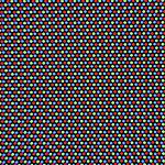
- Phosphor layer (screen) with red, green, and blue zones
- Close-up of the phosphor-coated inner side of the screen

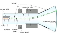
- Deflection coils
- Electron Beam and Electron Gun
- Focusing coil
- Phosphor layer on the inner side of the screen; emits light when struck by the electron beam
- Filament for heating the cathode
- Graphite layer on the inner side of the tube
- Rubber or silicone gasket where the anode voltage wire enters the tube (anode cup)
- Cathode
- Air-tight glass body of the tube
- Screen
- Coils in yoke
- Control electrode regulating the intensity of the electron beam and thereby the light emitted from the phosphor
- Contact pins for cathode, filament and control electrode
- Wire for anode high voltage