Cascode
Because there is no direct coupling from the output to input, the Miller effect is eliminated, contributing to a much higher bandwidth.
The name "cascode" was coined in an article written by Frederick Vinton Hunt and Roger Wayne Hickman in 1939, in a discussion on the application of voltage stabilizers.
[3] They proposed a cascade of two triodes (the first one with a common cathode setup, the second one with a common grid) as a replacement for a pentode, and so the name may be assumed to be an abbreviation of "casc(aded triode amplifier having characteristics similar to, but less noisy than, a single pent)ode".
[4] Cascode circuits were employed in early television sets for the 'front-end' or tuner because of their low noise and wider bandwidth.
While this can be overcome in radio frequency circuits/tuned circuits by "neutralising" feedback in opposition, it is more difficult to combat in wideband circuits such as video amplifiers, whose bandwidths range from analog television (some 5 MHz for PAL), to at least 86 MHz in the older VGA format (UXGA, 1600 × 1200, 60 Hz refresh).
Thus, the upper transistor permits the lower FET to operate with minimal negative (Miller) feedback, improving its bandwidth.
If the upper FET stage were operated alone using its source as input node (that is, common-gate (CG) configuration), it would have a good voltage gain and wide bandwidth.
Adding the lower FET results in a high input impedance, allowing the cascode stage to be driven by a high-impedance source.
The lower transistor has nearly constant voltage at both drain and source, and thus there is essentially "nothing" to feed back into its gate.
For the two-FET cascode, both transistors must be biased with ample VDS in operation, imposing a lower limit on the supply voltage.
Internally, there is one channel covered by the two adjacent gates; therefore, the resulting circuit is electrically a cascode composed of two FETs, the common lower-drain-to-upper-source connection merely being that portion of the single channel that lies physically adjacent to the border between the two gates.
This shows that a linear series voltage regulator is actually a current buffer with its input and output designations swapped.
For the bipolar transistor this product is (see hybrid-pi model): In a typical discrete bipolar device the Early voltage VA ≈ 100 V and the thermal voltage near room temperature is VT ≈ 25 mV, making gmrO ≈ 4000, a rather large number.
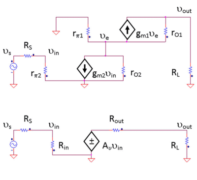
The g-parameters found in the above formulas can be used to construct a small-signal voltage amplifier with the same gain, input and output resistance as the original cascode (an equivalent circuit).
From the above amplifier characteristics, we see that Rin is infinite for the MOSFET cascode, so no attenuation of input signal occurs in that case.
In a similar fashion, the output signal from the equivalent circuit is In low-frequency circuits, a high voltage gain is typically desired, hence the importance of using a load with resistance RL >> Rout to avoid attenuation of the signal reaching the load.
In high frequency circuits, impedance matching at the input and output of the amplifier is typically desired in order to eliminate signal reflections and maximize power gain.
In the cascode, the isolation between the input and output ports is still characterized by a small reverse transmission term g12, making it easier to design matching networks because the amplifier is approximately unilateral.