Common emitter
The output of a common emitter amplifier is inverted; i.e. for a sine wave input signal, the output signal is 180 degrees out of phase with respect to the input.
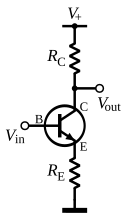
[1] In this circuit, the base terminal of the transistor serves as the input, the collector is the output, and the emitter is common to both (for example, it may be tied to ground reference or a power supply rail), hence its name.
Stability is another problem associated with such high-gain circuits due to any unintentional positive feedback that may be present.
Other problems associated with the circuit are the low input dynamic range imposed by the small-signal limit; there is high distortion if this limit is exceeded and the transistor ceases to behave like its small-signal model.
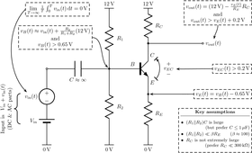
The voltage gain depends almost exclusively on the ratio of the resistors
The distortion and stability characteristics of the circuit are thus improved at the expense of a reduction in gain.
(While this is often described as "negative feedback", as it reduces gain, raises input impedance, and reduces distortion, it predates the invention of the negative feedback amplifier and does not reduce output impedance or increase bandwidth, as a true negative feedback amplifier would do.
[2]) At low frequencies and using a simplified hybrid-pi model, the following small-signal characteristics can be derived.
The bandwidth of the common-emitter amplifier tends to be low due to high capacitance resulting from the Miller effect.
[3] This large capacitor greatly decreases the bandwidth of the amplifier as it makes the time constant of the parasitic input RC filter
is the output impedance of the signal source connected to the ideal base.
The problem can be mitigated in several ways, including: The Miller effect negatively affects the performance of the common source amplifier in the same way (and has similar solutions).
The input signal is applied across the ground and the base circuit of the transistor.
Since the emitter is connected to the ground, it is common to signals, input and output.
In addition, higher voltage and power gains are usually obtained for common-emitter (CE) operation.
The output is an inverted copy of the AC component of the input that has been amplified by the ratio RC/RE and shifted by an amount determined by all four resistors.
Because RC is often large, the output impedance of this circuit can be prohibitively high.
[dubious – discuss] In this case it is common to replace the load resistor with a tuned circuit.
This may be done to limit the bandwidth to a narrow band centered around the intended operating frequency.