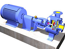
Centrifugal pump
[1] The fluid enters the pump impeller along or near to the rotating axis and is accelerated by the impeller, flowing radially outward into a diffuser or volute chamber (casing), from which it exits.
Common uses include water, sewage, agriculture, petroleum, and petrochemical pumping.
Centrifugal pumps are often chosen for their high flow rate capabilities, abrasive solution compatibility, mixing potential, as well as their relatively simple engineering.
[2] A centrifugal fan is commonly used to implement an air handling unit or vacuum cleaner.
According to Reti, the first machine that could be characterized as a centrifugal pump was a mud lifting machine which appeared as early as 1475 in a treatise by the Italian Renaissance engineer Francesco di Giorgio Martini.
[3] True centrifugal pumps were not developed until the late 17th century, when Denis Papin built one using straight vanes.
The curved vane was introduced by British inventor John Appold in 1851.
Fluid enters axially through eye of the casing, is caught up in the impeller blades, and is whirled tangentially and radially outward until it leaves through all circumferential parts of the impeller into the diffuser part of the casing.
The doughnut-shaped diffuser, or scroll, section of the casing decelerates the flow and further increases the pressure.
Accordingly, the change of the angular momentum is equal to the sum of the external moments.
act on an impeller or a diffuser, where: Since no pressure forces are created on cylindrical surfaces in the circumferential direction, it is possible to write Eq.
(1.13) Euler developed the head pressure equation created by the impeller see Fig.2.2
(2) the sum of 4 front element number call static pressure, the sum of last 2 element number call velocity pressure look carefully on the Fig 2.2 and the detail equation.
[clarification needed] The color triangle formed by velocity vectors
Fig 2.3 (a) shows the velocity triangle of a forward-curved vane impeller; Fig 2.3 (b) shows the velocity triangle of a radial straight-vane impeller.
) is a sum of the static lift, the head loss due to friction and any losses due to valves or pipe bends are all expressed in metres of fluid.
This style of pump uses no stuffing box to seal the shaft but instead utilizes a "throttle bushing".
Froth contains air that tends to block conventional pumps and cause loss of prime.
At each stage, the fluid is directed to the center before making its way to the discharge on the outer diameter.
The energy usage in a pumping installation is determined by the flow required, the height lifted and the length and friction characteristics of the pipeline.
The energy usage is determined by multiplying the power requirement by the length of time the pump is operating.
[9] They have no direct connection between the motor shaft and the impeller, so no stuffing box or gland is needed.
[citation needed] The process of filling the pump with liquid is called priming.
In normal conditions, common centrifugal pumps are unable to evacuate the air from an inlet line leading to a fluid level whose geodetic altitude is below that of the pump.
One of the first companies to market a self-priming centrifugal pump was American Marsh in 1938.
[11] In addition, a suction-side swing check valve or a vent valve must be fitted to prevent any siphon action and ensure that the fluid remains in the casing when the pump has been stopped.
The air escapes through the pump discharge nozzle whilst the fluid drops back down and is once more entrained by the impeller.
The design required for such a self-priming feature has an adverse effect on pump efficiency.
This design is not only used for its self-priming capabilities but also for its degassing effects when pumping two-phase mixtures (air/gas and liquid) for a short time in process engineering or when handling polluted fluids, for example, when draining water from construction pits.
This pump type operates without a foot valve and without an evacuation device on the suction side.