Current source
Figure 1 shows the schematic symbol for an ideal current source driving a resistive load.
An ideal current source is a mathematical model, which real devices can approach very closely.
Over a given load range, it is possible for some types of real current sources to exhibit nearly infinite internal resistance.
Thus, efficiency is low (due to power loss in the resistor) and it is usually impractical to construct a 'good' current source this way.
Nonetheless, it is often the case that such a circuit will provide adequate performance when the specified current and load resistance are small.
For example, a 5 V voltage source in series with a 4.7 kΩ resistor will provide an approximately constant current of 1 mA ± 5% to a load resistance in the range of 50 to 450 Ω.
They are implemented by active electronic components (transistors) having current-stable nonlinear output characteristic when driven by steady input quantity (current or voltage).
These circuits behave as dynamic resistors changing their present resistance to compensate current variations.
They are often used in place of ohmic resistors in analog integrated circuits (e.g., a differential amplifier) to generate a current that depends slightly on the voltage across the load.
Alternatively, an enhancement-mode N-channel MOSFET (metal–oxide–semiconductor field-effect transistor) could be used instead of a JFET in the circuits listed below for similar functionality.
As a result, the total current flowing through the load is constant and the circuit impedance seen by the input source is increased.
However the Howland current source isn't widely used because it requires the four resistors to be perfectly matched, and its impedance drops at high frequencies.
The voltage follower is loaded by a constant (current sensing) resistor acting as a simple current-to-voltage converter connected in the feedback loop.
Once the drain-source voltage reaches a certain minimum value, the JFET enters saturation where current is approximately constant.
A Zener diode, when reverse biased (as shown in the circuit) has a constant voltage drop across it irrespective of the current flowing through it.
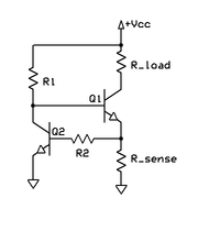
As long as the temperature remains constant (or doesn't vary much), the load current will be independent of the supply voltage, R1 and the transistor's gain.
R2 allows the load current to be set at any desirable value and is calculated by where VBE is typically 0.65 V for a silicon device.
Resistance R1 is calculated as where K = 1.2 to 2 (so that RR1 is low enough to ensure adequate IB), and hFE,min is the lowest acceptable current gain for the particular transistor type being used.
R1 is calculated as (the compensating diode's forward voltage drop, VD, appears in the equation and is typically 0.65 V for silicon devices.
If the power dissipation in the active device of the CCS is not small and/or insufficient emitter degeneration is used, this can become a non-trivial issue.
At room temperature there is about 0.6 V drop across the Vbe junction and hence 0.4 V across the emitter resistor, giving an approximate collector (load) current of 0.4/Re amps.
This creates a negative feedback loop within the circuit, which keeps the voltage at Q1's emitter almost exactly equal to the Vbe drop of Q2.
Since Q2 is dissipating very little power compared to Q1 (since all the load current goes through Q1, not Q2), Q2 will not heat up any significant amount and the reference (current setting) voltage across Rsense will remain steady at ≈0.6 V, or one diode drop above ground, regardless of the thermal changes in the Vbe drop of Q1.
The circuit is actually a buffered non-inverting amplifier driven by a constant input voltage.
As a result, the current flowing through the load is constant as well; it is exactly the Zener voltage divided by the sense resistor.
The transistor is not needed if the required current doesn't exceed the sourcing ability of the op-amp.
Nitrogen-filled glass tubes with two electrodes and a calibrated Becquerel (decays per second) amount of 226Ra offer a constant number of charge carriers per second for conduction, which determines the maximum current the tube can pass over a voltage range from 25 to 500 V.[7] Most sources of electrical energy (mains electricity, a battery, etc.)
An ideal voltage source loaded by an open circuit (i.e., an infinite impedance) will provide no current (and hence no power).
Real-world voltage sources instead have a non-zero output impedance, which is preferably very low (often much less than 1 ohm).
In the case of transistor current sources, impedances of a few megohms (at low frequencies) are typical.