Galvanometer
Early galvanometers were uncalibrated, but improved versions, called ammeters, were calibrated and could measure the flow of current more precisely.
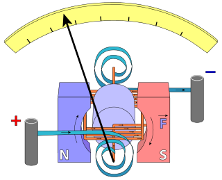
Galvanometers work by deflecting a pointer in response to an electric current flowing through a coil in a constant magnetic field.
Galvanometers came from the observation, first noted by Hans Christian Ørsted in 1820, that a magnetic compass's needle deflects when near a wire having electric current.
André-Marie Ampère, who gave mathematical expression to Ørsted's discovery, named the instrument after[1] the Italian electricity researcher Luigi Galvani, who in 1791 discovered the principle of the frog galvanoscope – that electric current would make the legs of a dead frog jerk.
Modern galvanometers, of the D'Arsonval/Weston type, are constructed with a small pivoting coil of wire, called a spindle, in the field of a permanent magnet.
Careful design of the pole pieces ensures that the magnetic field is uniform so that the angular deflection of the pointer is proportional to the current.
A meter can be calibrated as a DC voltmeter if the resistance of the coil is known by calculating the voltage required to generate a full-scale current.
The advantages of a digital instrument are higher precision and accuracy, but factors such as power consumption or cost may still favor the application of analog meter movements.
For example, for material processing with high-power lasers, closed loop mirror galvanometer mechanisms are used with servo control systems.
The closed loop is obtained measuring the position of the rotating axis with an infrared emitter and 2 photodiodes.
In analog strip chart recorders such as used in electrocardiographs, electroencephalographs and polygraphs, galvanometer mechanisms were used to position the pen.
Strip chart recorders with galvanometer driven pens may have a full-scale frequency response of 100 Hz and several centimeters of deflection.
Early designs increased the effect of the magnetic field generated by the current by using multiple turns of wire.
Originally, the instruments relied on the Earth's magnetic field to provide the restoring force for the compass needle.
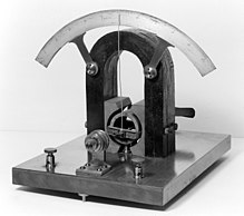
[3] Thomson's design was able to detect very rapid current changes by using small magnets attached to a lightweight mirror, suspended by a thread, instead of a compass needle.
The early moving-magnet form of galvanometer had the disadvantage that it was affected by any magnets or iron masses near it, and its deflection was not linearly proportional to the current.
This gap produced a consistent, radial magnetic field across the coil, giving a linear response throughout the instrument's range.
He substituted the fine wire suspension with a pivot and provided restoring torque and electrical connections[further explanation needed] through spiral springs rather than through the traditional wristwatch balance wheel hairspring.
To maintain the field strength, Weston's design used a very narrow circumferential slot through which the coil moved, with a minimal air-gap.
By 1888, Edward Weston had patented and brought out a commercial form of this instrument, which became a standard electrical equipment component.
Some galvanometers use a solid pointer on a scale to show measurements; other very sensitive types use a miniature mirror and a beam of light to provide mechanical amplification of low-level signals.
[7][8][9][10] A tangent galvanometer consists of a coil of insulated copper wire wound on a circular non-magnetic frame.
In operation, the instrument is first rotated until the magnetic field of the Earth, indicated by the compass needle, is parallel with the plane of the coil.
When used in this way, a low-voltage power source, such as a battery, is connected in series with a rheostat, the galvanometer, and an ammeter.
A beam of light reflected from the mirror falls on a graduated scale across the room, acting as a long mass-less pointer.
The mirror galvanometer was used as the receiver in the first trans-Atlantic submarine telegraph cables in the 1850s, to detect the extremely faint pulses of current after their thousand-mile journey under the Atlantic.
In a device called an oscillograph, the moving beam of light is used, to produce graphs of current versus time, by recording measurements on photographic film.
The moving part has a large moment of inertia that gives it an oscillation period long enough to make the integrated measurement.