Crystal twinning
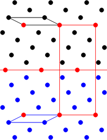
[1][2] On the microscopic level, the twin boundary is characterized by a set of atomic positions in the crystal lattice that are shared between the two orientations.
Contact twins meet on a single composition plane, often appearing as mirror images across the boundary.
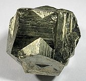
Closely spaced polysynthetic twinning is often observed as striations or fine parallel lines on the crystal face.
This type of twinning occurs around three, four, five, six, or eight-fold axes, the corresponding patterns are called threelings, fourlings, fivelings, sixlings, and eightlings.
[10][11] Rutile, aragonite, cerussite, and chrysoberyl often exhibit cyclic twinning, typically in a radiating pattern.
[15] For the five-fold case shown, there is a disclination along the common axis[16] which leads to an additional strain energy.
[22] Transformation and annealing twinning takes place when a cooling crystal experiences a displacive polymorphic transition.
This is typically polysynthetic twinning, which enables the crystal to maintain its isometric shape by averaging out the displacement in each direction.
Deformation twinning can be observed in a calcite cleavage fragment by applying gentle pressure with a knife blade near an edge.
It is believed that twinning is associated with dislocation motion on a coordinated scale, in contrast to slip, which is caused by independent glide at several locations in the crystal.
The deformation gradient can lead to fracture along the boundaries, particularly in bcc transition metals at low temperatures.
[25] If a metal with face-centered cubic (fcc) structure, like Al, Cu, Ag, Au, etc., is subjected to stress, it will experience twinning.
[26] Twin boundaries are partly responsible for shock hardening and for many of the changes that occur in cold work of metals with limited slip systems or at very low temperatures.
In certain types of high strength steels, very fine deformation twins act as primary obstacles against dislocation motion.
Deformation twins in Zr are generally lenticular in shape, lengthening in the 𝜼𝟏 direction and thickening along the 𝑲𝟏 plane normal.
The axis-angle misorientation relationship between the parent and twin is a rotation of angle 𝜉 about the shear plane's normal direction 𝑷.
[29] In addition to a homogeneous shear, atomic shuffles are sometimes required to reform the correct crystal structure in the twinned lattice.
[36] Experimental[37] and three-dimensional[38] analysis has focussed on the (stored) strain energy density measured along a path.
[41] The twin propagates when the homogeneous shear stress reaches a critical value, and a twin-parent interface advances inside the parent grain [240].
The propagating deformation twin generates a stress field due to its confinement by the surrounding parent crystal, and deformation twins develop a 3D oblate spheroid shape (which appears in 2D sections as a bi-convex lens) with a mixed coherent and non-coherent interface (Figure b).
[41] Kannan et al.[42] found, using in-situ ultra-high-speed optical imaging, that twin nucleation in single-crystal magnesium is stress-driven accompanied by instantaneous propagation at a speed of 1 km/s (initially) that prioritises volume lateral thickening over forward propagation, past a critical width where growth is then become faster along the shear direction.
[48] The twin thickness saturated once a critical residual dislocations’ density reached the coherent twin-parent crystal boundary.
This is especially important for materials where cleavage fracture can be initiated by twinning (e.g., iron-silicon, the ferrite phase of age-hardened duplex stainless-steel, and single-crystal magnesium) as a stress-relieving mechanism.
More recently, high-resolution electron backscatter diffraction (HR-EBSD) has been used to investigate the strain 'singularity' ahead of a twin tip in hexagonal close-packed (HCP) zirconium alloy.
The authors concluded that conditions at the twin tip control thickening and propagation in a manner analogous to the operation of dislocation sources ahead of a crack-tip.
However, the LSF analysis does not take advantage of the available full-field data, relies on global information on the applied stress, and does not consider the energy balance that drives twin growth.
Nanoscale testing (i.e., transmission electron microscopy) may not represent the behaviour in bulk samples due to plasticity starvation, i.e., large surface area to volume ratio,[59] so a suitable analysis method is needed.
Lloyd[49] described the stress concentration field ahead of the twin tip using a two-dimensional dislocation-based model within a single magnesium grain.
Wang and Li,[60] who considered microscopic phase-field (MPF) models of cracks, noted that the stress fields were similar for dislocations, deformation twinning and martensitic transformations, with differences only in the traction of the created surface, i.e., there is 100% traction recovery for dislocations and a traction-free surface for a crack.
Furthermore, Venables[63] noted that the oblate spheroid shape of the twin tip is the ideal example of an ellipsoid inclusion or a notch.