Directivity
In electromagnetics, directivity is a parameter of an antenna or optical system which measures the degree to which the radiation emitted is concentrated in a single direction.
[1] Directivity is an important measure because many antennas and optical systems are designed to radiate electromagnetic waves in a single direction or over a narrow-angle.
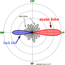
If an angle relative to the antenna is not specified, then directivity is presumed to refer to the axis of maximum radiation intensity.
is the radiation intensity, which is the power per unit solid angle; and
satisfy the relation that is, the total radiated power
represents the average power per unit solid angle.
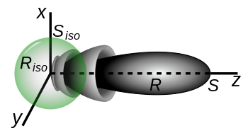
coordinate combination divided by what the radiation intensity would have been had the antenna been an isotropic antenna radiating the same amount of total power into space.
For a linear array the directivity will always be less than or equal to the number of elements.
For a standard linear array (SLA), where the element spacing is
, the directivity is equal to the inverse of the square of the 2-norm of the array weight vector, under the assumption that the weight vector is normalized such that its sum is unity.
[3] In the case of a uniformly weighted (un-tapered) SLA, this reduces to simply N, the number of array elements.
For a planar array, the computation of directivity is more complicated and requires consideration of the positions of each array element with respect to all the others and with respect to wavelength.
[4] For a planar rectangular or hexagonally spaced array with non-isotropic elements, the maximum directivity can be estimated using the universal ratio of effective aperture to directivity,
Note that for an un-tapered standard rectangular array (SRA), where
In the case of a sparse array, where element spacing
There is a physically intuitive reason for this relationship; essentially there are a limited number of photons per unit area to be captured by the individual antennas.
Conversely, if the antenna are more than a wavelength apart, there are photons that fall between the elements and are not collected at all.
Let's assume a 16×16 un-tapered standard rectangular array (which means that elements are spaced at
[6] The reason for this is that the effective aperture of the individual elements limits their directivity.
, thus creating tiny regions in the overall array where photons are missed, leading to
The result now should converge to N times the element gain, or
[8] For antenna arrays, the closed form expression for Directivity for progressively phased [9] array of isotropic sources will be given by,[10] where, Further studies on directivity expressions for various cases, like if the sources are omnidirectional (even in the array environment) like if the prototype element-pattern takes the form
, is defined as the solid angle which all power would flow through if the antenna radiation intensity were constant at its maximal value.
The beam solid angle can be approximated for antennas with one narrow major lobe and very negligible minor lobes by simply multiplying the half-power beamwidths (in radians) in two perpendicular planes.
degrees, then elementary integral calculus yields an expression for the directivity as The directivity is rarely expressed as the unitless number
but rather as a decibel comparison to a reference antenna: The reference antenna is usually the theoretical perfect isotropic radiator, which radiates uniformly in all directions and hence has a directivity of 1.
The calculation is therefore simplified to Another common reference antenna is the theoretical perfect half-wave dipole, which radiates perpendicular to itself with a directivity of 1.64: When polarization is taken under consideration, three additional measures can be calculated: Partial directive gain is the power density in a particular direction and for a particular component of the polarization, divided by the average power density for all directions and all polarizations.
For any pair of orthogonal polarizations (such as left-hand-circular and right-hand-circular), the individual power densities simply add to give the total power density.
Thus, if expressed as dimensionless ratios rather than in dB, the total directive gain is equal to the sum of the two partial directive gains.
[14] Partial directivity is calculated in the same manner as the partial directive gain, but without consideration of antenna efficiency (i.e. assuming a lossless antenna).