Drag (physics)
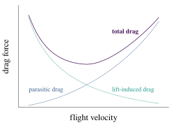
The combined overall drag curve therefore shows a minimum at some airspeed - an aircraft flying at this speed will be at or close to its optimal efficiency.
is the Reynolds number related to fluid path length L. As mentioned, the drag equation with a constant drag coefficient gives the force moving through fluid a relatively large velocity, i.e. high Reynolds number, Re > ~1000.
[14] For an object with a smooth surface, and non-fixed separation points (like a sphere or circular cylinder), the drag coefficient may vary with Reynolds number Re, up to extremely high values (Re of the order 107).
[15] [16] For an object with well-defined fixed separation points, like a circular disk with its plane normal to the flow direction, the drag coefficient is constant for Re > 3,500.
Under the assumption that the fluid is not moving relative to the currently used reference system, the power required to overcome the aerodynamic drag is given by:
When the fluid is moving relative to the reference system, for example, a car driving into headwind, the power required to overcome the aerodynamic drag is given by the following formula:
falling in air near Earth's surface at sea level, the terminal velocity is roughly equal to
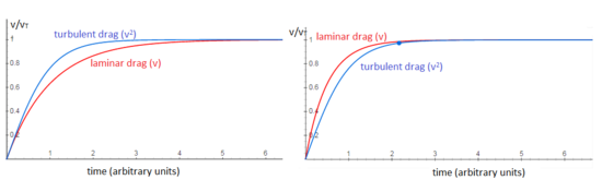
[18] The equation for viscous resistance or linear drag is appropriate for objects or particles moving through a fluid at relatively slow speeds (assuming there is no turbulence).
Using 10−3 Pa·s as the dynamic viscosity of water in SI units, we find a drag force of 0.09 pN.
The drag coefficient of a sphere can be determined for the general case of a laminar flow with Reynolds numbers less than
[22] Alternatively, calculated from the flow field perspective (far-field approach), the drag force results from three natural phenomena: shock waves, vortex sheet, and viscosity.
An alternative perspective on lift and drag is gained from considering the change of momentum of the airflow.
The change of momentum of the airflow downward results in a reduction of the rearward momentum of the flow which is the result of a force acting forward on the airflow and applied by the wing to the air flow; an equal but opposite force acts on the wing rearward which is the induced drag.
The shock waves induce changes in the boundary layer and pressure distribution over the body surface.
That is to say, the work the body does on the airflow is reversible and is recovered as there are no frictional effects to convert the flow energy into heat.
The idea that a moving body passing through air or another fluid encounters resistance had been known since the time of Aristotle.
[24] Louis Charles Breguet's paper of 1922 began efforts to reduce drag by streamlining.
Ludwig Prandtl's boundary layer theory in the 1920s provided the impetus to minimise skin friction.
He proposed an ideal aircraft that would have minimal drag which led to the concepts of a 'clean' monoplane and retractable undercarriage.
The aspect of Jones's paper that most shocked the designers of the time was his plot of the horse power required versus velocity, for an actual and an ideal plane.
By looking at a data point for a given aircraft and extrapolating it horizontally to the ideal curve, the velocity gain for the same power can be seen.
When Jones finished his presentation, a member of the audience described the results as being of the same level of importance as the Carnot cycle in thermodynamics.
In aerodynamics, wave drag consists of multiple components depending on the speed regime of the flight.
In transonic flight, wave drag is the result of the formation of shockwaves in the fluid, formed when local areas of supersonic (Mach number greater than 1.0) flow are created.
In highly supersonic flows, or in bodies with turning angles sufficiently large, unattached shockwaves, or bow waves will instead form.
Additionally, local areas of transonic flow behind the initial shockwave may occur at lower supersonic speeds, and can lead to the development of additional, smaller shockwaves present on the surfaces of other lifting bodies, similar to those found in transonic flows.
The closed form solution for the minimum wave drag of a body of revolution with a fixed length was found by Sears and Haack, and is known as the Sears-Haack Distribution.
Similarly, for a fixed volume, the shape for minimum wave drag is the Von Karman Ogive.
The Busemann biplane theoretical concept is not subject to wave drag when operated at its design speed, but is incapable of generating lift in this condition.
[29] The notion of boundary layers—introduced by Prandtl in 1904, founded on both theory and experiments—explained the causes of drag at high Reynolds numbers.