Reynolds number
These eddy currents begin to churn the flow, using up energy in the process, which for liquids increases the chances of cavitation.
The Reynolds number has wide applications, ranging from liquid flow in a pipe to the passage of air over an aircraft wing.
A region where these forces change behavior is known as a boundary layer, such as the bounding surface in the interior of a pipe.
[7] This ability to predict the onset of turbulent flow is an important design tool for equipment such as piping systems or aircraft wings, but the Reynolds number is also used in scaling of fluid dynamics problems and is used to determine dynamic similitude between two different cases of fluid flow, such as between a model aircraft, and its full-size version.
where: The Reynolds number can be defined for several different situations where a fluid is in relative motion to a surface.
This dimension is a matter of convention—for example radius and diameter are equally valid to describe spheres or circles, but one is chosen by convention.
For flow in a pipe, or for a sphere moving in a fluid, the internal diameter is generally used today.
The Reynolds number can be obtained when one uses the nondimensional form of the incompressible Navier–Stokes equations for a newtonian fluid expressed in terms of the Lagrangian derivative: Each term in the above equation has the units of a "body force" (force per unit volume) with the same dimensions of a density times an acceleration.
Finally, dropping the primes for ease of reading: This is why mathematically all Newtonian, incompressible flows with the same Reynolds number are comparable.
At the end of this pipe, there was a flow control valve used to vary the water velocity inside the tube.
When the velocity was low, the dyed layer remained distinct throughout the entire length of the large tube.
For flow in a pipe or tube, the Reynolds number is generally defined as[9] where For shapes such as squares, rectangular or annular ducts where the height and width are comparable, the characteristic dimension for internal-flow situations is taken to be the hydraulic diameter, DH, defined as where A is the cross-sectional area, and P is the wetted perimeter.
[13][14] At the lower end of this range, a continuous turbulent-flow will form, but only at a very long distance from the inlet of the pipe.
[15] For a fluid moving between two plane parallel surfaces—where the width is much greater than the space between the plates—then the characteristic dimension is equal to the distance between the plates.
Some texts then use a characteristic dimension that is four times the hydraulic radius, chosen because it gives the same value of Re for the onset of turbulence as in pipe flow,[17] while others use the hydraulic radius as the characteristic length-scale with consequently different values of Re for transition and turbulent flow.
Spheres are allowed to fall through the fluid and they reach the terminal velocity quickly, from which the viscosity can be determined.
[22] It has been used in yacht racing by owners who want to gain a speed advantage by pumping a polymer solution such as low molecular weight polyoxyethylene in water, over the wetted surface of the hull.
Inventions such as the "cavity transfer mixer" have been developed to produce multiple folds into a moving melt so as to improve mixing efficiency.
For grains in which measurement of each axis is impractical, sieve diameters are used instead as the characteristic particle length-scale.
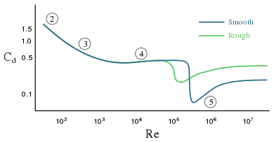
[27] Pressure drops[28] seen for fully developed flow of fluids through pipes can be predicted using the Moody diagram which plots the Darcy–Weisbach friction factor f against Reynolds number Re and relative roughness ε/D.
The diagram clearly shows the laminar, transition, and turbulent flow regimes as Reynolds number increases.
The model numbers and design numbers should be in the same proportion, hence This allows engineers to perform experiments with reduced scale models in water channels or wind tunnels and correlate the data to the actual flows, saving on costs during experimentation and on lab time.
For experimental flow modeling to be useful, it requires a fair amount of experience and judgment of the engineer.
The size of the largest scales of fluid motion (sometimes called eddies) are set by the overall geometry of the flow.
It is at these small scales where the dissipation of energy by viscous action finally takes place.
Using the definition of the Reynolds number we can see that a large diameter with rapid flow, where the density of the blood is high, tends towards turbulence.
In the latter case, an artificial viscosity is reduced to a nonlinear mechanism of energy distribution in complex network media.
Reynolds number then represents a basic control parameter that expresses a balance between injected and dissipated energy flows for an open boundary system.
It has been shown that Reynolds critical regime separates two types of phase space motion: accelerator (attractor) and decelerator.
[38] High Reynolds number leads to a chaotic regime transition only in frame of strange attractor model.


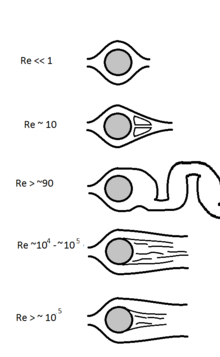
- attached flow ( Stokes flow ) and steady separated flow ,
- separated unsteady flow, having a laminar flow boundary layer upstream of the separation, and producing a vortex street ,
- separated unsteady flow with a laminar boundary layer at the upstream side, before flow separation, with downstream of the sphere a chaotic turbulent wake ,
- post-critical separated flow, with a turbulent boundary layer.