Electromagnetic induction
[5][6] In Faraday's first experimental demonstration, on August 29, 1831,[7] he wrapped two wires around opposite sides of an iron ring or "torus" (an arrangement similar to a modern toroidal transformer).
[citation needed] Based on his understanding of electromagnets, he expected that, when current started to flow in one wire, a sort of wave would travel through the ring and cause some electrical effect on the opposite side.
He saw a transient current, which he called a "wave of electricity", when he connected the wire to the battery and another when he disconnected it.
[8] This induction was due to the change in magnetic flux that occurred when the battery was connected and disconnected.
For example, he saw transient currents when he quickly slid a bar magnet in and out of a coil of wires, and he generated a steady (DC) current by rotating a copper disk near the bar magnet with a sliding electrical lead ("Faraday's disk").
However, scientists at the time widely rejected his theoretical ideas, mainly because they were not formulated mathematically.
[10] An exception was James Clerk Maxwell, who used Faraday's ideas as the basis of his quantitative electromagnetic theory.
[10][11][12] In Maxwell's model, the time varying aspect of electromagnetic induction is expressed as a differential equation, which Oliver Heaviside referred to as Faraday's law even though it is slightly different from Faraday's original formulation and does not describe motional emf.
In 1834 Heinrich Lenz formulated the law named after him to describe the "flux through the circuit".
Lenz's law gives the direction of the induced emf and current resulting from electromagnetic induction.
Faraday's law of induction makes use of the magnetic flux ΦB through a region of space enclosed by a wire loop.
where dA is an element of the surface Σ enclosed by the wire loop, B is the magnetic field.
When the flux through the surface changes, Faraday's law of induction says that the wire loop acquires an electromotive force (emf).
[22][23] This is believed to be a unique example in physics of where such a fundamental law is invoked to explain two such different phenomena.
[24] Albert Einstein noticed that the two situations both corresponded to a relative movement between a conductor and a magnet, and the outcome was unaffected by which one was moving.
[25] The principles of electromagnetic induction are applied in many devices and systems, including: The emf generated by Faraday's law of induction due to relative movement of a circuit and a magnetic field is the phenomenon underlying electrical generators.
When a permanent magnet is moved relative to a conductor, or vice versa, an electromotive force is created.
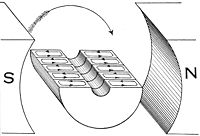
A different implementation of this idea is the Faraday's disc, shown in simplified form on the right.
Eddy currents flow in closed loops in planes perpendicular to the magnetic field.
Cores for these devices use a number of methods to reduce eddy currents: Eddy currents occur when a solid metallic mass is rotated in a magnetic field, because the outer portion of the metal cuts more magnetic lines of force than the inner portion; hence the induced electromotive force is not uniform; this tends to cause electric currents between the points of greatest and least potential.
Eddy currents consume a considerable amount of energy and often cause a harmful rise in temperature.
In practical use, the number of laminations or punchings ranges from 40 to 66 per inch (16 to 26 per centimetre), and brings the eddy current loss down to about one percent.
[26] This is a rotor approximately 20 mm in diameter from a DC motor used in a CD player.
Note the laminations of the electromagnet pole pieces, used to limit parasitic inductive losses.
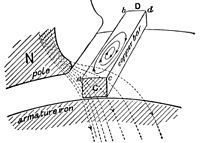
In this illustration, a solid copper bar conductor on a rotating armature is just passing under the tip of the pole piece N of the field magnet.