Heat sink
A heat sink is designed to maximize its surface area in contact with the cooling medium surrounding it, such as the air.
Air velocity, choice of material, protrusion design and surface treatment are factors that affect the performance of a heat sink.
Heat sink attachment methods and thermal interface materials also affect the die temperature of the integrated circuit.
A heat sink transfers thermal energy from a higher-temperature device to a lower-temperature fluid medium.
The power supplies of electronics are not absolutely efficient, so extra heat is produced that may be detrimental to the function of the device.
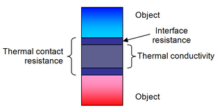
Applying the conservation of energy, for steady-state conditions, and Newton's law of cooling to the temperature nodes shown in the diagram gives the following set of equations: where Using the mean air temperature is an assumption that is valid for relatively short heat sinks.
The above equations show that: Natural convection requires free flow of air over the heat sink.
For semiconductor devices used in a variety of consumer and industrial electronics, the idea of thermal resistance simplifies the selection of heat sinks.
[6] Aluminium alloy 1050 has one of the higher thermal conductivity values at 229 W/(m·K) and heat capacity of 922 J/(kg·K),[7] but is mechanically soft.
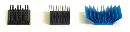
One-piece aluminium heat sinks can be made by extrusion, casting, skiving or milling.
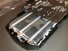
They found that for low air approach velocity, typically around 1 m/s, the thermal performance is at least 20% better than straight fin heat sinks.
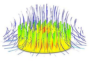
The concept of a pin fin heat sink is to pack as much surface area into a given volume as possible, while working in any orientation of fluid flow.
When both of these temperatures are on the order of 0 °C to 100 °C, the contribution of radiation compared to convection is generally small, and this factor is often neglected.
In this case, finned heat sinks operating in either natural-convection or forced-flow will not be affected significantly by surface emissivity.
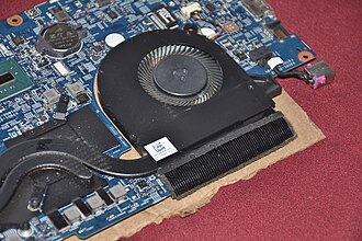
To ensure that the component does not overheat, a thermal engineer seeks to find an efficient heat transfer path from the device to the environment.
Concerning the latter, the component must remain in thermal contact with its heat sink with reasonable shock and vibration.
The most typical damage caused by rework is the separation of the component die heat spreader from its package.
More expensive than tape and epoxy, wire form z-clips attach heat sinks mechanically.
In addition to the mechanical attachment that the z-clip provides, it also permits using higher-performance thermal interface materials, such as phase change types.
The clips make use of the gap created by the ball grid array (BGA) between the component underside and PCB top surface.
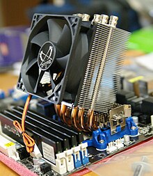
For larger heat sinks and higher preloads, push pins with compression springs are very effective.
For very large heat sinks, there is no substitute for the threaded standoff and compression spring attachment method.
Thermal contact resistance occurs due to the voids created by surface roughness effects, defects and misalignment of the interface.
[11] If the contact area is small, as it is for rough surfaces, the major contribution to the resistance is made by the gaps.
In the simplest case, this means partially gripping a component using a heavy metal crocodile clip, hemostat, or similar clamp.
On the other hand, electrical components such as magnetic reed switches can malfunction if exposed to hotter soldering irons, so this practice is still very much in use.
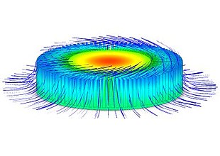
Due to the complex nature of the highly 3D flow in present applications, numerical methods or computational fluid dynamics (CFD) can also be used.
The heat sink system curve can be calculated by the flow resistance of the channels and inlet and outlet losses as done in standard fluid mechanics text books, such as Potter, et al.[27] and White.
CFD can give an insight into flow patterns that are difficult, expensive or impossible to study using experimental methods.
Simulations can give a prediction of flow phenomena using CFD software for all desired quantities, with high resolution in space and time and virtually any problem and realistic operating conditions.