Induction motor
Three-phase squirrel-cage induction motors are widely used as industrial drives because they are self-starting, reliable, and economical.
Single-phase induction motors are used extensively for smaller loads, such as garbage disposals and stationary power tools.
VFD offers energy savings opportunities for induction motors in applications like fans, pumps, and compressors that have a variable load.
By manually turning switches on and off, Walter Baily demonstrated this in 1879, effectively the first primitive induction motor.
[12][18][19][20] Steadfast in his promotion of three-phase development, Mikhail Dolivo-Dobrovolsky invented the cage-rotor induction motor in 1889 and the three-limb transformer in 1890.
[21][22] Furthermore, he claimed that Tesla's motor was not practical because of two-phase pulsations, which prompted him to persist in his three-phase work.
[12] By 1896, General Electric and Westinghouse signed a cross-licensing agreement for the bar-winding-rotor design, later called the squirrel-cage rotor.
[12] Arthur E. Kennelly was the first to bring out the full significance of complex numbers (using j to represent the square root of minus one) to designate the 90º rotation operator in analysis of AC problems.
The difference, or "slip," between actual and synchronous speed varies from about 0.5% to 5.0% for standard Design B torque curve induction motors.
The generating mode for induction motors is complicated by the need to excite the rotor, which begins with only residual magnetization.
Therefore, it is necessary to either snap the motor and connect it momentarily to a live grid or to add capacitors charged initially by residual magnetism and providing the required reactive power during operation.
This industry standard method of counting poles results in the same synchronous speed for a given frequency regardless of polarity.
[37] The typical speed-torque relationship of a standard NEMA Design B polyphase induction motor is as shown in the curve at right.
Suitable for most low performance loads such as centrifugal pumps and fans, Design B motors are constrained by the following typical torque ranges:[30][b] Over a motor's normal load range, the torque's slope is approximately linear or proportional to slip because the value of rotor resistance divided by slip,
A resistance start design uses a starter inserted in series with the startup winding, creating reactance.
Although polyphase motors are inherently self-starting, their starting and pull-up torque design limits must be high enough to overcome actual load conditions.
Before the development of semiconductor power electronics, it was difficult to vary the frequency, and cage induction motors were mainly used in fixed speed applications.
Applications, such as electric overhead cranes, used DC drives or wound rotor motors (WRIM) with slip rings for rotor circuit connection to variable external resistance allowing considerable range of speed control.
However, resistor losses associated with low speed operation of WRIMs is a major cost disadvantage, especially for constant loads.
By the turn of this century, however, such cascade-based electromechanical systems became much more efficiently and economically solved using power semiconductor elements solutions.
[41] In many industrial variable-speed applications, DC and WRIM drives are being displaced by VFD-fed cage induction motors.
[43] The stator of an induction motor consists of poles carrying supply current to induce a magnetic field that penetrates the rotor.
[44] The method of changing the direction of rotation of an induction motor depends on whether it is a three-phase or single-phase machine.
Motors required to change direction regularly (such as hoists) will have extra switching contacts in their controller to reverse rotation as needed.
A variable frequency drive nearly always permits reversal by electronically changing the phase sequence of voltage applied to the motor.
Some motors bring out the start winding connections to allow selection of rotation direction at installation.
[47] Full-load motor efficiency ranges from 85–97%, with losses as follows:[48] For an electric motor, the efficiency, represented by the Greek letter Eta,[49] is defined as the quotient of the mechanical output power and the electric input power,[50] calculated using this formula: Regulatory authorities in many countries have implemented legislation to encourage the manufacture and use of higher efficiency electric motors.
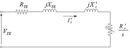
The equivalent circuit is a single-phase representation of a multiphase induction motor that is valid in steady-state balanced-load conditions.
The Steinmetz equivalent circuit is expressed simply in terms of the following components: Paraphrasing from Alger in Knowlton, an induction motor is simply an electrical transformer the magnetic circuit of which is separated by an air gap between the stator winding and the moving rotor winding.
[39][46][51][52][53][54] The following rule-of-thumb approximations apply to the circuit:[54][55][56] Motor input equivalent impedance Stator current Rotor current referred to the stator side in terms of stator current From Steinmetz equivalent circuit, we have That is, air gap power is equal to electromechanical power output plus rotor copper losses Expressing electromechanical power output in terms of rotor speed Expressing