Integrated Truss Structure
All truss components were named after their planned end-positions: Z for zenith, S for starboard and P for port, with the number indicating the sequential position.
The S0 truss might be considered a misnomer, as it is mounted centrally on the zenith position of Destiny and is neither starboard nor port side.
While the bulk of the Z1 truss is unpressurized, it features a Common Berthing Mechanism (CBM) port that connects its nadir to the zenith port of Unity and contains a small pressurized dome that allowed astronauts to connect electrical ground straps between Unity and the truss without an EVA.
[4] This MBM is not a port and is not pressurized or electrically powered, but it can be operated with a handheld tool to berth any passive CBM to it.
In December 2008, the Ad Astra Rocket Company announced an agreement with NASA to place a flight test version of its VASIMR ion thruster on the station to take over reboost duties.
A NASA spokesperson stated that the ISS "was not an ideal demonstration platform for the desired performance level of the engines".
Detailed design, test, and construction of the S1 and P1 structures were conducted by McDonnell Douglas (now Boeing) in Huntington Beach, CA.
The P2 and S2 trusses were planned as locations for rocket thrusters in the original design for Space Station Freedom.
[9] The P3/P4 truss assembly was installed by the Space Shuttle Atlantis STS-115 mission, launched September 9, 2006, and attached to the P1 segment.
Upon its installation, no power was flowing across the rotary joint, so the electricity generated by the P4 solar array wings was only being used on the P4 segment and not the rest of the station.
The primary functions of the P3 truss segment are to provide mechanical, power and data interfaces to payloads attached to the two UCCAS platforms; axial indexing for solar tracking, or rotating of the arrays to follow the sun, via the SARJ; movement and worksite accommodations for the Mobile Transporter.
[11] The S3 truss also supports EXPRESS Logistics Carrier locations, first to be launched and installed in the 2009 time frame.
Major subsystems of the P4 and S4 Photovoltaic Modules (PVM) include the two Solar Array Wings (SAW), the Photovoltaic Radiator (PVR), the Alpha Joint Interface Structure (AJIS), and Modified Rocketdyne Truss Attachment System (MRTAS), and Beta Gimbal Assembly (BGA).
[citation needed] Over time, the photovoltaic cells on the wings have degraded gradually, having been designed for a 15-year service life.
Work to install support brackets for the new arrays on the P6 truss mast cans was initiated by the members of Expedition 64.
[13] Work to install and deploy the first two arrays themselves on the P6 brackets was successfully conducted over three spacewalks by Shane Kimbrough and Thomas Pesquet of Expedition 65.
[14][15][16] In November and December 2022, astronauts Francisco Rubio and Josh A. Cassada of Expedition 68 installed the second set of brackets and arrays, one each on the P4 and S4 Trusses.
[17][18][19][20] In June 2023, astronauts Stephen Bowen and Warren Hoburg of Expedition 69 installed the third set of brackets and arrays, one each on the S6 and S4 Trusses.
When in operation, these joints continuously rotate to keep the solar array wings on the outboard truss segments oriented towards the Sun.
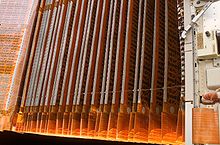
Each SARJ is 10 feet in diameter, weighs approximately 2,500 pounds and can be rotated continuously using bearing assemblies and a servo control system.
On both the port and starboard sides, all of the power flows through the Utility Transfer Assembly (UTA) in the SARJ.
[11] The Solar Alpha Rotary Joints contain Drive Lock Assemblies which allow the outer segments of the ITS to rotate and track the Sun.
The SSU has an overvoltage protection feature to maintain the output voltage below 200 V DC maximum for all operating conditions.
[39] Beyond the rails Canadarm2 can step over the alpha rotary joint and relocate to grapple fixtures on the S6 and P6 truss.
During STS-120 Astronaut Scott Parazynski rode the Orbiter Boom Sensor to repair a tear in the 4B solar array.
The first truss segment to be launched was Z1, which was mounted to the Unity module's zenith (facing away from Earth) Common Berthing Mechanism.