Kirchhoff's circuit laws
Kirchhoff's circuit laws are two equalities that deal with the current and potential difference (commonly known as voltage) in the lumped element model of electrical circuits.
These laws can be applied in time and frequency domains and form the basis for network analysis.
Both of Kirchhoff's laws can be understood as corollaries of Maxwell's equations in the low-frequency limit.
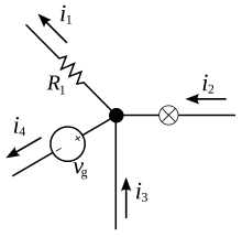
This law, also called Kirchhoff's first law, or Kirchhoff's junction rule, states that, for any node (junction) in an electrical circuit, the sum of currents flowing into that node is equal to the sum of currents flowing out of that node; or equivalently: The algebraic sum of currents in a network of conductors meeting at a point is zero.Recalling that current is a signed (positive or negative) quantity reflecting direction towards or away from a node, this principle can be succinctly stated as:
where n is the total number of branches with currents flowing towards or away from the node.
Kirchhoff's circuit laws were originally obtained from experimental results.
[2][3] This means that the current law relies on the fact that the net charge in the wires and components is constant.
A matrix version of Kirchhoff's current law is the basis of most circuit simulation software, such as SPICE.
The current law is applicable to any lumped network irrespective of the nature of the network; whether unilateral or bilateral, active or passive, linear or non-linear.
A similar derivation can be found in The Feynman Lectures on Physics, Volume II, Chapter 22: AC Circuits.
Approximate the circuit with lumped elements, so that time-varying magnetic fields are contained to each component and the field in the region exterior to the circuit is negligible.
Note that this derivation uses the following definition for the voltage rise from
However, the electric potential (and thus voltage) can be defined in other ways, such as via the Helmholtz decomposition.
In the low-frequency limit, the voltage drop around any loop is zero.
In the low-frequency limit, this is a corollary of Faraday's law of induction (which is one of Maxwell's equations).
This has practical application in situations involving "static electricity".
The current law is dependent on the assumption that the net charge in any wire, junction or lumped component is constant.
Whenever the electric field between parts of the circuit is non-negligible, such as when two wires are capacitively coupled, this may not be the case.
This occurs in high-frequency AC circuits, where the lumped element model is no longer applicable.
[4] For example, in a transmission line, the charge density in the conductor may be constantly changing.
On the other hand, the voltage law relies on the fact that the actions of time-varying magnetic fields are confined to individual components, such as inductors.
The lumped element approximation for a circuit is accurate at low frequencies.
At higher frequencies, leaked fluxes and varying charge densities in conductors become significant.
To an extent, it is possible to still model such circuits using parasitic components.
If frequencies are too high, it may be more appropriate to simulate the fields directly using finite element modelling or other techniques.
To model circuits so that both laws can still be used, it is important to understand the distinction between physical circuit elements and the ideal lumped elements.
Unlike an ideal conductor, wires can inductively and capacitively couple to each other (and to themselves), and have a finite propagation delay.
Real conductors can be modeled in terms of lumped elements by considering parasitic capacitances distributed between the conductors to model capacitive coupling, or parasitic (mutual) inductances to model inductive coupling.
Assume an electric network consisting of two voltage sources and three resistors.
The current i3 has a negative sign which means the assumed direction of i3 was incorrect and i3 is actually flowing in the direction opposite to the red arrow labeled i3.
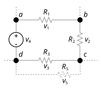
v 1 + v 2 + v 3 + v 4 = 0
