The linkage consists of the frame, a crank, two grounded rockers, and two couplers all connected by pivot joints.
[3][4][5][6] The proportions of each of the links in the mechanism are defined to optimize the linearity of the foot for one-half of the rotation of the crank.
The remaining rotation of the crank allows the foot to be raised to a predetermined height before returning to the starting position and repeating the cycle.
Two of these linkages coupled together at the crank and one-half cycle out of phase with each other will allow the frame of a vehicle to travel parallel to the ground.
It can step over curbs, climb stairs, or travel into areas that are currently not accessible with wheels but does not require microprocessor control or multitudes of actuator mechanisms.
Underwater walking robot, using Klann leg linkages in laser-cut and anodised aluminium.
[
1
]
These figures show a single linkage in the fully extended, mid-stride, retracted, and lifted positions of the walking cycle. These four figures show the crank (rightmost link in the first figure on the left with the extended pin) in the 0, 90, 180, and 270 degree positions.
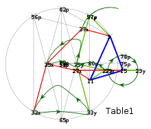
This is a repeating animation of the legs in motion with the near legs of each set outlined in blue. A reasonable understanding of the functioning of the linkage can be gained by focusing on a specific point and following it through several cycles. Each of the pivot points is displayed in green. The three positions grounded to the frame for each leg are stationary. The upper and lower rockers move back and forth along a fixed arc and the crank traces out a circle.
Movement paths of each point (in blue is the ground link)