Lift (force)
Planing lift, in which only the lower portion of the body is immersed in a liquid flow, is used by motorboats, surfboards, windsurfers, sailboats, and water-skis.
The lift discussed in this article is mainly in relation to airfoils; marine hydrofoils and propellers share the same physical principles and work in the same way, despite differences between air and water such as density, compressibility, and viscosity.
Most simplified explanations follow one of two basic approaches, based either on Newton's laws of motion or on Bernoulli's principle.
According to Newton's second law, this change in flow direction requires a downward force applied to the air by the airfoil.
[4] Some versions of the flow-deflection explanation of lift cite the Coandă effect as the reason the flow is able to follow the convex upper surface of the airfoil.
It is in this broader sense that the Coandă effect is used by some popular references to explain why airflow remains attached to the top side of an airfoil.
It argues that the curved upper surface acts as more of an obstacle to the flow, forcing the streamlines to pinch closer together, making the streamtubes narrower.
[52] Reduced upper-surface pressure and upward lift follow from the higher speed by Bernoulli's principle, just as in the equal transit time explanation.
For conventional wings that are flat on the bottom and curved on top this makes some intuitive sense, but it does not explain how flat plates, symmetric airfoils, sailboat sails, or conventional airfoils flying upside down can generate lift, and attempts to calculate lift based on the amount of constriction or obstruction do not predict experimental results.
[4] As explained below under a more comprehensive physical explanation, producing a lift force requires maintaining pressure differences in both the vertical and horizontal directions.
[59] Lift is a result of pressure differences and depends on angle of attack, airfoil shape, air density, and airspeed.
[73][74] Under usual flight conditions, the boundary layer remains attached to both the upper and lower surfaces all the way to the trailing edge, and its effect on the rest of the flow is modest.
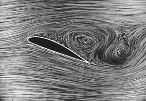
As the angle of attack is increased, a point is reached where the boundary layer can no longer remain attached to the upper surface.
When the boundary layer separates, it leaves a region of recirculating flow above the upper surface, as illustrated in the flow-visualization photo at right.
[76] The flow around bluff bodies – i.e. without a streamlined shape, or stalling airfoils – may also generate lift, in addition to a strong drag force.
Interaction of the object's flexibility with the vortex shedding may enhance the effects of fluctuating lift and cause vortex-induced vibrations.
Here the mechanical rotation acts on the boundary layer, causing it to separate at different locations on the two sides of the cylinder.
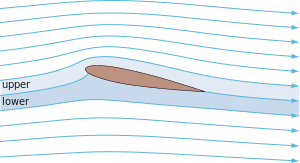
An airfoil affects the speed and direction of the flow over a wide area, producing a pattern called a velocity field.
Some explanations that refer to the "Coandă effect" suggest that viscosity plays a key role in the downward turning, but this is false.
[99][100] In principle, the NS equations, combined with boundary conditions of no through-flow and no slip at the airfoil surface, could be used to predict lift with high accuracy in any situation in ordinary atmospheric flight.
Predicting lift by solving the NS equations in their raw form would require the calculations to resolve the details of the turbulence, down to the smallest eddy.
[102][103] A RANS solution consists of the time-averaged velocity vector, pressure, density, and temperature defined at a dense grid of points surrounding the airfoil.
Further simplification is available through potential flow theory, which reduces the number of unknowns to be determined, and makes analytic solutions possible in some cases, as described below.
Either Euler or potential-flow calculations predict the pressure distribution on the airfoil surfaces roughly correctly for angles of attack below stall, where they might miss the total lift by as much as 10–20%.
In potential-flow theory, the flow is assumed to be irrotational, i.e. that small fluid parcels have no net rate of rotation.
The incompressible-potential-flow equation can also be solved by conformal mapping, a method based on the theory of functions of a complex variable.
In particular, if the Kutta condition is met, in which the rear stagnation point moves to the airfoil trailing edge and attaches there for the duration of flight, the lift can be calculated theoretically through the conformal mapping method.
The lift generated by a conventional airfoil is dictated by both its design and the flight conditions, such as forward velocity, angle of attack and air density.
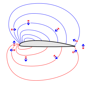
After the flow leaves the trailing edge, this difference in velocity takes place across a relatively thin shear layer called a vortex sheet.
For a flat horizontal rectangle that is much longer than it is tall, the fluxes of vertical momentum through the front and back are negligible, and the lift is accounted for entirely by the integrated pressure differences on the top and bottom.