Flow separation
[1] A boundary layer exists whenever there is relative movement between a fluid and a solid surface with viscous forces present in the layer of fluid close to the surface.
A reasonable assessment of whether the boundary layer will be laminar or turbulent can be made by calculating the Reynolds number of the local flow conditions.
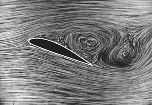
[2][3] The flow becomes detached from the surface, and instead takes the forms of eddies and vortices.
[4] In aerodynamics, flow separation results in reduced lift and increased pressure drag, caused by the pressure differential between the front and rear surfaces of the object.
In internal passages separation causes stalling and vibrations in machinery blading and increased losses (lower efficiency) in inlets and compressors.
Much effort and research has gone into the design of aerodynamic and hydrodynamic surface contours and added features which delay flow separation and keep the flow attached for as long as possible.
Examples include the fur on a tennis ball, dimples on a golf ball, turbulators on a glider, which induce an early transition to turbulent flow; vortex generators on aircraft.
The streamwise momentum equation inside the boundary layer is approximately stated as where
[5] The tendency of a boundary layer to separate primarily depends on the distribution of the adverse or negative edge velocity gradient
In contrast, the separation resistance of a laminar boundary layer is independent of Reynolds number — a somewhat counterintuitive fact.
[8] Another effect of boundary layer separation is regular shedding vortices, known as a Kármán vortex street.
Vortices shed from the bluff downstream surface of a structure at a frequency depending on the speed of the flow.
Vortex shedding produces an alternating force which can lead to vibrations in the structure.
These vibrations could be established and reflected at different frequencies based on their origin in adjacent solid or fluid bodies and could either damp or amplify the resonance.