Linear induction motor
A feasible linear induction motor is described in US patent 782312 (1905; inventor Alfred Zehden of Frankfurt-am-Main), and is for driving trains or lifts.
[4] In the late 1940s, professor Eric Laithwaite of Imperial College in London developed the first full-size working model.
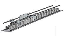
[5] A linear induction motor's primary typically consists of a flat magnetic core (generally laminated) with transverse slots that are often straight cut[6] with coils laid into the slots, with each phase giving an alternating polarity so that the different phases physically overlap.
These poles are typically made either with a suitably cut laminated backing plate or a series of transverse U-cores.
where fs is supply frequency in Hz, p is the number of poles, and ns is the synchronous speed of the magnetic field in revolutions per second.
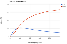
[1] Similarly, the efficiency during generator operation (electric braking/recuperating) with a linear induction motor was reported as relatively low due to end effects.
However, linear induction motors can avoid the need for gearboxes and similar drivetrains, and these have their own losses; and working knowledge of the importance of the goodness factor can minimise the effects of the larger air gap.
Because of these properties, linear motors are often used in maglev propulsion, as in the Japanese Linimo magnetic levitation train line near Nagoya.
[12] The length of the track was 600 metres (2,000 ft), and trains "flew" at an altitude of 15 millimetres (0.59 in), levitated by electromagnets, and propelled with linear induction motors.
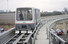
[14] However, linear motors have been used independently of magnetic levitation, such as Tokyo's Toei Ōedo Line.
They are also used by the SkyTrain (Vancouver), the Tomorrowland Transit Authority PeopleMover at Walt Disney World Resort in Bay Lake, Florida, and the Subway people mover at George Bush Intercontinental Airport in Houston, Texas, which uses the same design.
These specialized devices have been used to provide direct X-Y motion for precision laser cutting of cloth and sheet metal, automated drafting, and cable forming.
Linear induction motors are also used in looms, magnetic levitation enable bobbins to float between the fibers without direct contact.