m-derived filter
[2] The main problem being addressed was the need to achieve a better match of the filter into the terminating impedances.
In general, all filters designed by the image method fail to give an exact match, but the m-type filter is a big improvement with suitable choice of the parameter m. The m-type filter section has a further advantage in that there is a rapid transition from the cut-off frequency of the passband to a pole of attenuation just inside the stopband.
For this reason, filters designed using m-type sections are often designed as composite filters with a mixture of k-type and m-type sections and different values of m at different points to get the optimum performance from both types.
This pre-dated George Campbell's publication of his constant k-type design in 1922 on which the m-type filter is based.
[6] Zobel published the image analysis theory of m-type filters in 1923.
[7] Once popular, M-type filters and image parameter designed filters in general are now rarely designed, having been superseded by more advanced network synthesis methods.
[8] The building block of m-derived filters, as with all image impedance filters, is the "L" network, called a half-section and composed of a series impedance Z, and a shunt admittance Y.
The starting point of the design is the values of Z and Y derived from the constant k prototype and are given by where k is the nominal impedance of the filter, or R0.
[11] For the low-pass half section shown, the cut-off frequency of the m-type is the same as the k-type and is given by The pole of attenuation occurs at; From this it is clear that smaller values of m will produce
There is also a practical limit to how small m can be made due to the inherent resistance of the inductors.
[11][12][13] The following expressions for image impedances are all referenced to the low-pass prototype section.
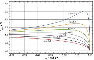
From the chart it can be seen that in the passband the closest impedance match to a constant pure resistance termination occurs at approximately m = 0.6.
[14] For an m-derived section in general the transmission parameters for a half-section are given by[14] and for n half-sections For the particular example of the low-pass L section, the transmission parameters solve differently in three frequency bands.
The prototype has a cut-off frequency of ωc = 1 rad/s and a nominal impedance R0 = 1 Ω.
Further additions of half-sections to either of these forms a ladder network which may start and end with series or shunt elements.
It is usual to provide half half-sections at the ends of the filter with m = 0.6 as this value gives the flattest Zi in the passband and hence the best match in to a resistive termination.