NAND gate
A LOW (0) output results only if all the inputs to the gate are HIGH (1); if any input is LOW (0), a HIGH (1) output results.
A NAND gate is made using transistors and junction diodes.
By De Morgan's laws, a two-input NAND gate's logic may be expressed as
Digital systems employing certain logic circuits take advantage of NAND's functional completeness.
The basic implementations can be understood from the image on the left below: If either of the switches S1 or S2 is open, the pull-up resistor R will set the output signal Q to 1 (high).
If S1 and S2 are both closed, the pull-up resistor will be overridden by the switches, and the output will be 0 (low).
In the depletion-load NMOS logic realization in the middle below, the switches are the transistors T2 and T3, and the transistor T1 fulfills the function of the pull-up resistor.
This is due to the faster charge mobility in n-MOSFETs compared to p-MOSFETs, so that the parallel connection of two p-MOSFETs (T1 and T2) realised in the NAND gate is more favourable than their series connection in the NOR gate.
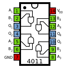
The standard, 4000 series, CMOS IC is the 4011, which includes four independent, two-input, NAND gates.
[2] An entire processor can be created using NAND gates alone.