Quadrupole ion trap
They are also called radio frequency (RF) traps or Paul traps in honor of Wolfgang Paul, who invented the device[1][2] and shared the Nobel Prize in Physics in 1989 for this work.
[3] It is used as a component of a mass spectrometer or a trapped ion quantum computer.
A charged particle, such as an atomic or molecular ion, feels a force from an electric field.
It is not possible to create a static configuration of electric fields that traps the charged particle in all three directions (this restriction is known as Earnshaw's theorem).
It is possible, however, to create an average confining force in all three directions by use of electric fields that change in time.
To do so, the confining and anti-confining directions are switched at a rate faster than it takes the particle to escape the trap.
[4] There are two main classes of traps, depending on whether the oscillating field provides confinement in three or two dimensions.
In the two-dimension case (a so-called "linear RF trap"), confinement in the third direction is provided by static electric fields.
The ions are trapped in the space between these three electrodes by AC (oscillating) and DC (static) electric fields.
The AC radio frequency voltage oscillates between the two hyperbolic metal end cap electrodes if ion excitation is desired; the driving AC voltage is applied to the ring electrode.
The use of damping gas and the mass-selective instability mode developed by Stafford et al. led to the first commercial 3D ion traps.
[6] The advantage of the linear design is its greater storage capacity (in particular of Doppler-cooled ions) and its simplicity, but this leaves a particular constraint on its modeling.
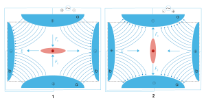
The Paul trap is designed to create a saddle-shaped field to trap a charged ion, but with a quadrupole, this saddle-shaped electric field cannot be rotated about an ion in the centre.
For this reason, the motions of a single ion in the trap are described by Mathieu equations, which can only be solved numerically by computer simulations.
The intuitive explanation and lowest order approximation is the same as strong focusing in accelerator physics.
Since the field affects the acceleration, the position lags behind (to lowest order by half a period).
So the particles are at defocused positions when the field is focusing and vice versa.
Ions in a quadrupole field experience restoring forces that drive them back toward the center of the trap.
This equation can be exactly solved using the Floquet theorem or the standard techniques of multiple scale analysis.
[12] Advantages of the linear trap design are increased ion storage capacity, faster scan times, and simplicity of construction (although quadrupole rod alignment is critical, adding a quality control constraint to their production.
[13] The cylindrical ion trap (CIT) emerged as a derivative of the quadrupole ion trap with simpler geometric structure in which the electrodes are arranged in a cylindrical shape rather than the traditional hyperbolic or linear configuration.
By applying a combination of static (DC) and oscillating (RF) voltages to these electrodes, a three-dimensional quadrupole field is generated.
[15] Ion traps with a cylindrical rather than a hyperbolic ring electrode[16][17][18][19][20] have been developed and microfabricated in arrays to develop miniature mass spectrometers for chemical detection in medical diagnosis and other fields.
[14] Quadrupole traps can also be "unfolded" to create the same effect using a set of planar electrodes.
[21] This trap geometry can be made using standard micro-fabrication techniques, including the top metal layer in a standard CMOS microelectronics process,[22] and is a key technology for scaling trapped ion quantum computers to useful numbers of qubits.
But in certain applications like antihydrogen production it is important to confine two species of charged particles of widely varying masses.
To achieve this objective, a uniform magnetic field is added in the axial direction of the quadrupole ion trap.
A DIT is driven by digital signals, typically rectangular waveforms[24][25] that are generated by switching rapidly between discrete voltage levels.
Major advantages of the DIT are its versatility[26] and virtually unlimited mass range.
The digital ion trap has been developed mainly as a mass analyzer.