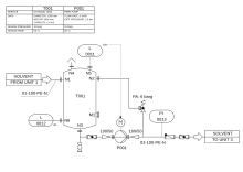
Piping and instrumentation diagram
P&IDs also play a significant role in the maintenance and modification of the process after initial build.
Modifications are red-penned onto the diagrams and are vital records of the current plant design.
They are also vital in enabling development of; P&IDs form the basis for the live mimic diagrams displayed on graphical user interfaces of large industrial control systems such as SCADA and distributed control systems.
Based on STANDARD ANSI/ISA S5.1 and ISO 14617-6, the P&ID is used for the identification of measurements within the process.
Prior to the advent of computer-aided design (CAD) in the late 1980s, P&IDs were drawn by hand.