Polarizer
When the two polarization states are relative to the direction of a surface (usually found with Fresnel reflection), they are usually termed s and p. This distinction between Cartesian and s–p polarization can be negligible in many cases, but it becomes significant for achieving high contrast and with wide angular spreads of the incident light.
Its current H-sheet form is made from polyvinyl alcohol (PVA) plastic with an iodine doping.
The durability and practicality of Polaroid makes it the most common type of polarizer in use, for example for sunglasses, photographic filters, and liquid crystal displays.
A modern type of absorptive polarizer is made of elongated silver nano-particles embedded in thin (≤0.5 mm) glass plates.
[5] Such glass polarizers perform best for long-wavelength infrared light, and are widely used in fiber-optic communication.
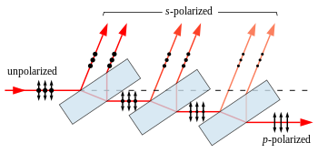
A simple linear polarizer can be made by tilting a stack of glass plates at Brewster's angle to the beam.
[6] Adding more plates and reducing the angle allows a better compromise between transmission and polarization to be achieved.
In these crystals, a beam of unpolarized light incident on their surface is split by refraction into two rays.
A Nicol prism was an early type of birefringent polarizer, that consists of a crystal of calcite which has been split and rejoined with Canada balsam.
At the internal interface, an unpolarized beam splits into two linearly polarized rays which leave the prism at a divergence angle of 15°–45°.
Thin-film linear polarizers (also known as TFPN) are glass substrates on which a special optical coating is applied.
Either Brewster's angle reflections or interference effects in the film cause them to act as beam-splitting polarizers.
Since the electrons are free to move in this direction, the polarizer behaves in a similar manner to the surface of a metal when reflecting light, and the wave is reflected backwards along the incident beam (minus a small amount of energy lost to Joule heating of the wire).
Overall, this causes the transmitted wave to be linearly polarized with an electric field completely perpendicular to the wires.
Therefore, it is relatively easy to construct wire-grid polarizers for microwaves, far-infrared, and mid-infrared radiation.
In addition, advanced lithographic techniques can also build very tight pitch metallic grids (typ.
Since the degree of polarization depends little on wavelength and angle of incidence, they are used for broad-band applications such as projection.
A beam of unpolarized light can be thought of as containing a uniform mixture of linear polarizations at all possible angles.
If the two axes are orthogonal, the polarizers are crossed and in theory no light is transmitted, though again practically speaking no polarizer is perfect and the transmission is not exactly zero (for example, crossed Polaroid sheets appear slightly blue in colour because their extinction ratio is better in the red).
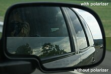
They are used as polarizing filters in photography to reduce oblique reflections from non-metallic surfaces, and are the lenses of the 3D glasses worn for viewing some stereoscopic movies (notably, the RealD 3D variety), where the polarization of light is used to differentiate which image should be seen by the left and right eye.
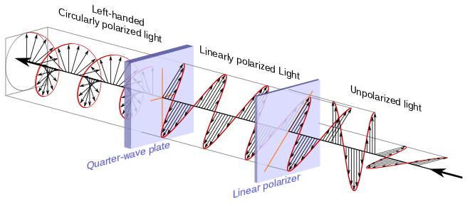
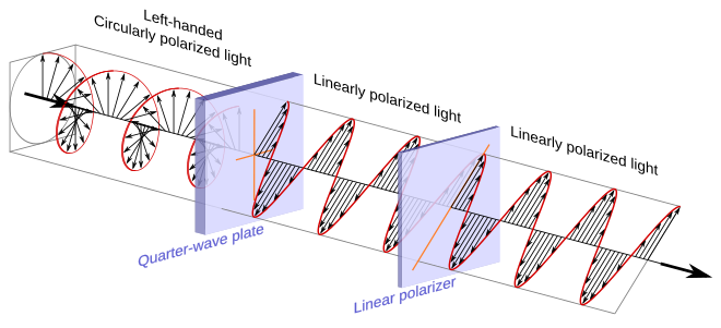
The transmission axis of the linear polarizer needs to be half way (45°) between the fast and slow axes of the quarter-wave plate.
In the arrangement above, the transmission axis of the linear polarizer is at a positive 45° angle relative to the right horizontal and is represented with an orange line.
In the illustration toward the right is the electric field of the linearly polarized light just before it enters the quarter-wave plate.
Directly below it, for comparison purposes, is the linearly polarized light that entered the quarter-wave plate.
Similarly this light is considered counter-clockwise circularly polarized because if a stationary observer faces against the direction of travel, the person will observe its electric field rotate in the counter-clockwise direction as the wave passes a given point in space.
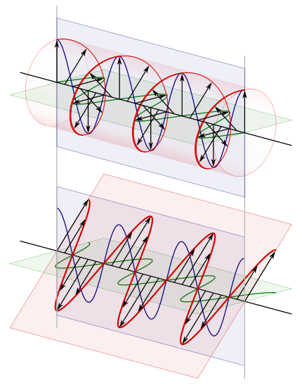
In trying to appreciate how the quarter-wave plate transforms the linearly polarized light, it is important to realize that the two components discussed are not entities in and of themselves but are merely mental constructs one uses to help appreciate what is happening.
First, given the dual usefulness of this image, begin by imagining the circularly polarized light displayed at the top as still leaving the quarter-wave plate and traveling toward the left.
This brings the two components back into their initial phase relationship, reestablishing the selected circular polarization.
However, cameras with through-the-lens metering (TTL) and autofocusing systems – that is, all modern SLR and DSLR – rely on optical elements that pass linearly polarized light.
If light entering the camera is already linearly polarized, it can upset the exposure or autofocus systems.