Matched Z-transform method
The matched Z-transform method, also called the pole–zero mapping[1][2] or pole–zero matching method,[3] and abbreviated MPZ or MZT,[4] is a technique for converting a continuous-time filter design to a discrete-time filter (digital filter) design.
The method works by mapping all poles and zeros of the s-plane design to z-plane locations
must be adjusted to normalize the desired gain, typically set to match the analog filter's gain at DC by setting
axis around the z-plane's unit circle repeatedly, any zeros (or poles) greater than the Nyquist frequency will be mapped to an aliased location.
may optionally be shifted down to the Nyquist frequency by putting them at
in much the same manner as with the bilinear transform (BLT).
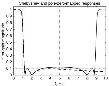
[1][3][6][7] While this transform preserves stability and minimum phase, it preserves neither time- nor frequency-domain response and so is not widely used.
[4] MZT does provide less high frequency response error than the BLT, however, making it easier to correct by adding additional zeros, which is called the MZTi (for "improved").
[9] A specific application of the matched Z-transform method in the digital control field is with the Ackermann's formula, which changes the poles of the controllable system; in general from an unstable (or nearby) location to a stable location.