Power factor
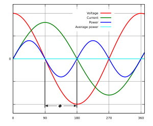
Real power is the average of the instantaneous product of voltage and current and represents the capacity of the electricity for performing work.
Power-factor correction increases the power factor of a load, improving efficiency for the distribution system to which it is attached.
Linear loads with a low power factor (such as induction motors) can be corrected with a passive network of capacitors or inductors.
The devices for correction of the power factor may be at a central substation, spread out over a distribution system, or built into power-consuming equipment.
In a purely resistive AC circuit, voltage and current waveforms are in step (or in phase), changing polarity at the same instant in each cycle.
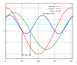
We can conclude that the mathematical relationship between these components is: As the angle θ increases with fixed total apparent power, current and voltage are further out of phase with each other.
Capacitive loads such as capacitor banks or buried cables generate reactive power with the current phase leading the voltage.
This apparent power must be produced and transmitted to the load and is subject to losses in the production and transmission processes.
Compensating elements near an electrical load will reduce the apparent power demand on the supply system.
The reactive elements in power factor correction devices can create voltage fluctuations and harmonic noise when switched on or off.
They will supply or sink reactive power regardless of whether there is a corresponding load operating nearby, increasing the system's no-load losses.
An automatic power factor correction unit consists of some capacitors that are switched by means of contactors.
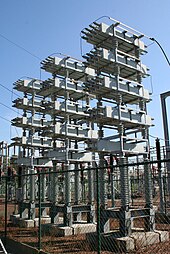
In place of a set of switched capacitors, an unloaded synchronous motor can supply reactive power.
Synchronous condensers are often used in connection with high-voltage direct-current transmission projects or in large industrial plants such as steel mills.
These systems are able to compensate sudden changes of power factor much more rapidly than contactor-switched capacitor banks and, being solid-state, require less maintenance than synchronous condensers.
Filters consisting of linear capacitors and inductors can prevent harmonic currents from entering the supplying system.
This simplification is often a good approximation for stiff voltage sources (not being affected by changes in load downstream in the distribution network).
This could overload the neutral wire in some cases and create error in kilowatt-hour metering systems and billing revenue.
Eddy current losses generally increase as the square of the frequency, lowering the transformer's efficiency, dissipating additional heat, and reducing its service life.
In generators and motors, these currents produce magnetic fields which oppose the rotation of the shaft and sometimes result in damaging mechanical vibrations.
In the case of a switched-mode power supply, a boost converter is inserted between the bridge rectifier and the main input capacitors.
Another switched-mode converter inside the power supply produces the desired output voltage from the DC bus.
This approach requires additional semiconductor switches and control electronics but permits cheaper and smaller passive components.
[27] DPFC uses semiconductor switches, typically thyristors, to quickly connect and disconnect capacitors or inductors to improve power factor.
Alternatively, all components of the system such as generators, conductors, transformers, and switchgear would be increased in size (and cost) to carry the extra current.
When the power factor is close to unity, for the same kVA rating of the transformer more load current can be supplied.
With the rising cost of energy and concerns over the efficient delivery of power, active PFC has become more common in consumer electronics.
The field coils are connected either directly to polyphase voltage sources or to a phase-shifting reactor if a single-phase application.
This type of instrument can be made to register for currents in both directions, giving a four-quadrant display of power factor or phase angle.
More sophisticated versions measure the peak of the fundamental harmonic only, thus giving a more accurate reading for phase angle on distorted waveforms.