Push–pull output
Symmetrical construction of the two sides of the amplifier means that even-order harmonics are cancelled, which can reduce distortion.
[5] By using a pair of low-power vacuum tubes in push–pull configuration, the amplifier allowed the use of a loudspeaker instead of headphones, while providing acceptable battery life with low standby power consumption.
[6] The technique continues to be used in audio, radio frequency, digital and power electronics systems today.
Because of the way these circuits are drawn schematically, with two transistors stacked vertically, normally with a level shifting diode in between, they are called "totem pole" outputs.
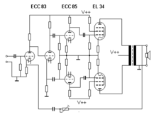
A transformer allows a single polarity power supply to be used, but limits the low-frequency response of the amplifier.
Similarly, with a single power supply, a capacitor can be used to block the DC level at the output of the amplifier.
Also, the driving circuit can have silicon diodes mounted in thermal contact with the output transistors to provide compensation.
This type of arrangement tends to give lower distortion than quasi-symmetric stages because even harmonics are cancelled more effectively with greater symmetry.
Using a bridge-tied load arrangement allows a much greater degree of matching between positive and negative halves, compensating for the inevitable small differences between NPN and PNP devices.
These amplifiers were first designed long before the development of solid-state electronic devices; they are still in use by both audiophiles and musicians who consider them to sound better.
[citation needed] The phase-splitter stage is usually another vacuum tube but a transformer with a center-tapped secondary winding was occasionally used in some designs.
A Single Ended Push–Pull (SEPP, SRPP or mu-follower[10]) output stage, originally called the Series-Balanced amplifier (US patent 2,310,342, Feb 1943).
The drive to each tube therefore might not be equal, but the circuit tends to keep the current through the bottom device somewhat constant throughout the signal, increasing the power gain and reducing distortion compared with a true single-tube single-ended output stage.
The bottom tube acts part way between a constant current sink and an equal partner in the push–pull workload.
A so-called ultra-linear push–pull amplifier uses either pentodes or tetrodes with their screen grid fed from a percentage of the primary voltage on the output transformer.