Microwave cavity
A microwave cavity acts similarly to a resonant circuit with extremely low loss at its frequency of operation, resulting in quality factors (Q factors) up to the order of 106, for copper cavities, compared to 102 for circuits made with separate inductors and capacitors at the same frequency.
Other loss mechanisms exist in evacuated cavities, for example the multipactor effect or field electron emission.
Eventually the electrons strike the walls of the cavity and lose their energy.
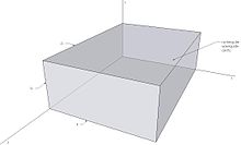
Depending on the resonance transverse mode, transverse cavity dimensions may be constrained to expressions related to geometric functions, or to zeros of Bessel functions or their derivatives (see below), depending on the symmetry properties of the cavity's shape.
Alternately it follows that cavity length must be an integer multiple of half-wavelength at resonance (see page 451 of Ramo et al[2]).
Loaded cavities usually have lower symmetries and compromise certain performance indicators, such as the best Q factor.
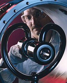
[4] The figure from the U.S. Department of Energy shows a multi-cell superconducting cavity in a clean room at Fermi National Accelerator Laboratory.A microwave cavity has a fundamental mode, which exhibits the lowest resonant frequency of all possible resonant modes.
The precise resonant frequency of a loaded cavity must be calculated using finite element methods for Maxwell's equations with boundary conditions.
Loaded cavities are particularly suited for accelerating low velocity charged particles.
For a cavity with high degrees of symmetry, using analytical expressions of the electric and magnetic field, surface currents in the conducting walls and electric field in dielectric lossy material.
[14] For cavities with arbitrary shapes, finite element methods for Maxwell's equations with boundary conditions must be used.
An external power source is usually coupled to the cavity by a small aperture, a small wire probe or a loop, see page 563 of Ramo et al.[2] External coupling structure has an effect on cavity performance and needs to be considered in the overall analysis, see Montgomery et al page 232.
resonant mode can be found by imposing boundary conditions on electromagnetic field expressions.
follow from the solutions of a cylindrical waveguide with additional electric boundary conditions at the position of the enclosing plates.
of a cavity can be decomposed into three parts, representing different power loss mechanisms.
Total Q factor of the cavity can be found as in page 567 of Ramo et al [2]
Microwave resonant cavities can be represented and thought of as simple LC circuits, see Montgomery et al pages 207-239.
mode can be written as given in Montgomery et al page 209[15] where V is the cavity volume,
Conventional inductors are usually wound from wire in the shape of a helix with no core.
In addition, capacitance between turns causes dielectric losses in the insulation which coats the wires.
These effects make the high frequency resistance greater and decrease the Q factor.
Conventional capacitors use air, mica, ceramic or perhaps teflon for a dielectric.
Even if the Q factor of VHF inductors and capacitors is high enough to be useful, their parasitic properties can significantly affect their performance in this frequency range.
The shunt capacitance of an inductor may be more significant than its desirable series inductance.
The series inductance of a capacitor may be more significant than its desirable shunt capacitance.
Dielectric loss of air is extremely low for high-frequency electric or magnetic fields.
Air-filled microwave cavities confine electric and magnetic fields to the air spaces between their walls.
Silver or gold plating prevents oxidation and reduces electrical losses in cavity walls.
Even though gold is not quite as good a conductor as copper, it still prevents oxidation and the resulting deterioration of Q factor over time.
Some satellite resonators are silver-plated and covered with a gold flash layer.
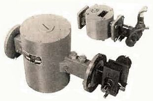

(1) A setscrew trimmer capacitor used to adjust the frequency
(2) The top of the GS13-1 ( Russian : ГС-13-1 [ 1 ] ) triode which generates the microwaves
(3) A wire coupling loop from which the output power is taken