RS-25
Fuel (liquid hydrogen) and oxidizer (liquid oxygen) from the Space Shuttle's external tank entered the orbiter at the umbilical disconnect valves and from there flowed through the orbiter's main propulsion system (MPS) feed lines; whereas in the Space Launch System (SLS), fuel and oxidizer from the rocket's core stage flow directly into the MPS lines.
Fuel in the nozzle cooling and chamber coolant valve systems is then sent via pre-burners into the HPFTP turbine and HPOTP before being reunited again in the hot gas manifold, from where it passes into the MCC injectors.
A number of baffles of various types are present inside the accumulator to control sloshing and turbulence, which is useful of itself and also to prevent the escape of gas into the low-pressure oxidizer duct to be ingested in the HPOTP.
The main pump boosts the liquid oxygen's pressure from 2.9 to 30 MPa (420 to 4,350 psi) while operating at approximately 28,120 rpm, giving a power output of 23,260 hp (17.34 MW).
[4] The low-pressure fuel turbopump (LPFTP) is an axial-flow pump driven by a two-stage turbine powered by gaseous hydrogen.
It boosts the pressure of the liquid hydrogen from 1.9 to 45 MPa (276 to 6,515 psia), and operates at approximately 35,360 rpm with a power of 71,140 hp (53.05 MW).
A small portion of the flow from the LPFTP is then directed to a common manifold from all three engines to form a single path to the liquid hydrogen tank to maintain pressurization.
The pre-burners produce the fuel-rich hot gases that pass through the turbines to generate the power needed to operate the high-pressure turbopumps.
[4] The engine's main combustion chamber (MCC) receives fuel-rich hot gas from a hot-gas manifold cooling circuit.
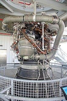
[4] The MCC comprises a structural shell made of Inconel 718 which is lined with a copper-silver-zirconium alloy called NARloy-Z, developed specifically for the RS-25 in the 1970s.
[8][9] An alternative for the construction of RS-25 engines to be used in SLS missions is the use of advanced structural ceramics, such as thermal barrier coatings (TBCs) and ceramic-matrix composites (CMCs).
[10] These materials possess significantly lower thermal conductivities than metallic alloys, thus allowing more efficient combustion and reducing the cooling requirements.
Further, CMCs have been studied as a replacement for Ni-based superalloys and are composed of high-strength fibers (BN, C) continuously dispersed in a SiC matrix.
An MCC composed of a CMC, though less studied and farther from fruition than the application of a TBC, could offer unprecedented levels of engine efficiency.
[13] The inner surface of each nozzle is cooled by liquid hydrogen flowing through brazed stainless steel tube wall coolant passages.
On the Space Shuttle, a support ring welded to the forward end of the nozzle is the engine attach point to the orbiter-supplied heat shield.
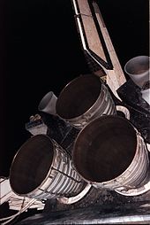
Thermal protection is necessary because of the exposure portions of the nozzles experience during the launch, ascent, on-orbit and entry phases of a mission.
During the investigation of the Challenger accident the two MECs (from engines 2020 and 2021), recovered from the seafloor, were delivered to Honeywell Aerospace for examination and analysis.
The comparatively large gimbal range is necessary to correct for the pitch momentum that occurs due to the constantly shifting center of mass as the vehicle burns fuel in flight and after booster separation.
At the conclusion of the study, P&W put forward a proposal for a 250,000 lbf engine called the XLR-129, which used a two-position expanding nozzle to provide increased efficiency over a wide range of altitudes.
[23][24] In January 1969 NASA awarded contracts to General Dynamics, Lockheed, McDonnell Douglas, and North American Rockwell to initiate the early development of the Space Shuttle.
[25] As part of these 'Phase A' studies, the involved companies selected an upgraded version of the XLR-129, developing 415,000 lbf (1,850 kN), as the baseline engine for their designs.
[12] Rocketdyne, P&W and Aerojet General were selected to receive funding although, given P&W's already-advanced development (demonstrating a working 350,000 lbf (1,600 kN) concept engine during the year) and Aerojet General's prior experience in developing the 1,500,000 lbf (6,700 kN) M-1 engine, Rocketdyne was forced to put a large amount of private money into the design process to allow the company to catch up to its competitors.
[12] During the year-long 'Phase B' study period, Rocketdyne was able to make use of their experience developing the HG-3 engine to design their SSME proposal, producing a prototype by January 1971.
The engine made use of a new Rocketdyne-developed copper-zirconium alloy (called NARloy-Z) and was tested on February 12, 1971, producing a chamber pressure of 3,172 psi (21,870 kPa).
The first set of engines (2005, 2006 and 2007) was delivered to Kennedy Space Center in 1979 and installed on Columbia, before being removed in 1980 for further testing and reinstalled on the orbiter.
The engines would maintain this power level until around T+40 seconds, where they would be throttled back to around 70% to reduce aerodynamic loads on the shuttle stack as it passed through the region of maximum dynamic pressure, or max.
[59] In addition to the RS-25Ds, the SLS program makes use of the Main Propulsion Systems (MPS, the "plumbing" feeding the engines) from the three remaining shuttle orbiters for testing purposes (having been removed as part of the orbiters' decommissioning), with the first two launches (Artemis I and Artemis II) originally predicted to make use of the MPS hardware from Space Shuttles Atlantis and Endeavour in their core stages.
[65] On 29 August 2022, Artemis I was delayed by a problem with engineering sensors on RS-25D #3 (serial number E2058) erroneously reporting that it hadn't chilled down to its ideal operating temperature.
[67] In 2015, a test campaign was conducted to determine RS-25 engine performance with a new engine controller unit, under lower liquid-oxygen temperatures, with greater inlet pressure due to the taller SLS core-stage liquid-oxygen tank and higher vehicle acceleration; and with more nozzle heating due to the four-engine configuration and its position in-plane with the SLS booster exhaust nozzles.