Stub (electronics)
The free end of the stub is either left open-circuit, or short-circuited (as is always the case for waveguides).
Neglecting transmission line losses, the input impedance of the stub is purely reactive; either capacitive or inductive, depending on the electrical length of the stub, and on whether it is open or short circuit.
Stubs may thus function as capacitors, inductors and resonant circuits at radio frequencies.
Their reactive properties are determined by their physical length in relation to the wavelength of the radio waves.
[1] They are often used to replace discrete capacitors and inductors, because at UHF and microwave frequencies lumped components perform poorly due to parasitic reactance.
Stub circuits can be designed using a Smith chart, a graphical tool which can determine what length line to use to obtain a desired reactance.
The input impedance of a lossless, short circuited line is, where Thus, depending on whether
is positive or negative, the short circuited stub will be inductive or capacitive, respectively.
is then given by: the length of a stub to act as an inductor L at the same frequency is given by: where in both equations, n is an integer number of half-wavelengths (possibly zero) that can be arbitrarily added to the line without changing the impedance.
The input impedance of a lossless open circuit stub is given by where the symbols
The length of an open circuit stub to act as an inductor L at an angular frequency of
is: the length of an open circuit stub to act as a capacitor C at the same frequency is: where again, n is an arbitrary whole number of half-wavelengths that can be inserted into the segment (including zero).
The impedance will not continue to rise monotonically with frequency after resonance as in a lumped tuned circuit.
This response of the stub continues to repeat with increasing frequency alternating between resonance and anti-resonance.
The length of the stub is chosen so that it exactly cancels the reactive part of the presented impedance.
[3] A single stub will only achieve a perfect match at one specific frequency.
Several stubs may be used spaced along the main transmission line for wideband matching.
The resulting transmission function of the network has a passband ripple like the Chebyshev filter, but the ripples never reach 0 dB insertion loss at any point in the passband, as they would do for the standard filter.
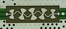
[4] Radial stubs are a planar component that consists of a sector of a circle rather than a constant-width line.
They are used with planar transmission lines when a low impedance stub is required.
Filter circuits using stubs often use them in pairs, one connected to each side of the main line.