Rectifier
Many applications of rectifiers, such as power supplies for radio, television and computer equipment, require a steady constant DC voltage (as would be produced by a battery).
[1] The first vacuum tube diodes designed for rectifier application in power supply circuits were introduced in April 1915 by Saul Dushman of General Electric.
Other devices that have control electrodes as well as acting as unidirectional current valves are used where more than simple rectification is required—e.g., where variable output voltage is needed.
Most low power rectifiers for domestic equipment are single-phase, but three-phase rectification is very important for industrial applications and for the transmission of energy as DC (HVDC).
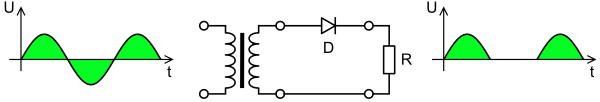
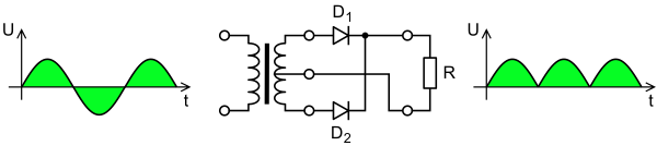
Full-wave rectification converts both polarities of the input waveform to pulsating DC (direct current), and yields a higher average output voltage.
For single-phase AC, if the transformer is center-tapped, then two diodes back-to-back (cathode-to-cathode or anode-to-anode, depending on output polarity required) can form a full-wave rectifier.
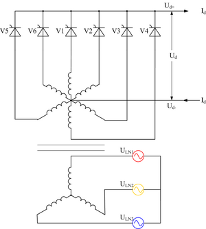
This type of rectifier is said to have a pulse-number of three, since the output voltage on the DC side contains three distinct pulses per cycle of the grid frequency:
[6] This was because the three or six AC supply inputs could be fed to a corresponding number of anode electrodes on a single tank, sharing a common cathode.
Some commercially available double diodes have all four terminals available so the user can configure them for single-phase split supply use, half a bridge, or three-phase rectifier.
: If the three-phase bridge rectifier is operated symmetrically (as positive and negative supply voltage), the center point of the rectifier on the output side (or the so-called isolated reference potential) opposite the center point of the transformer (or the neutral conductor) has a potential difference in the form of a triangular common-mode voltage.
Diode voltage multipliers, frequently used as a trailing boost stage or primary high voltage (HV) source, are used in HV laser power supplies, powering devices such as cathode-ray tubes (CRT) (like those used in CRT based television, radar and sonar displays), photon amplifying devices found in image intensifying and photo multiplier tubes (PMT), and magnetron based radio frequency (RF) devices used in radar transmitters and microwave ovens.
Peak loss is very important for low voltage rectifiers (for example, 12 V or less) but is insignificant in high-voltage applications such as HVDC power transmission systems.
In practice, most smoothing filters utilize multiple components to efficiently reduce ripple voltage to a level tolerable by the circuit.
Transformer internal impedance modifies the reservoir capacitor waveform, changes the peak voltage, and introduces regulation issues.
A disadvantage of a resistor input filter is that it consumes power in the form of waste heat that is not available to the load, so it is employed only in low current circuits.
An active regulator employs reactive components to store and discharge energy, so that most or all current supplied by the rectifier is passed to the load.
Gate turn-off thyristors are used to produce alternating current from a DC supply, for example on the Eurostar Trains to power the three-phase traction motors.
Mechanical rectifiers used some form of rotation or resonant vibration driven by electromagnets, which operated a switch or commutator to reverse the current.
These mechanical rectifiers were noisy and had high maintenance requirements, including lubrication and replacement of moving parts due to wear.
The motor spins in time with the AC frequency and periodically reverses the connections to the load at an instant when the sinusoidal current goes through a zero-crossing.
These consisted of a resonant reed, vibrated by an alternating magnetic field created by an AC electromagnet, with contacts that reversed the direction of the current on the negative half cycles.
Similar electrolytic devices were used as lightning arresters around the same era by suspending many aluminium cones in a tank of triammonium orthophosphate solution.
The most powerful mercury-arc rectifiers ever built were installed in the Manitoba Hydro Nelson River Bipole HVDC project, with a combined rating of more than 1 GW and 450 kV.
They are rarely able to handle currents exceeding 250 mA owing to the limits of plate power dissipation, and cannot be used for low voltage applications, such as battery chargers.
Once common until replaced by more compact and less costly silicon solid-state rectifiers in the 1970s, these units used stacks of oxide-coated metal plates and took advantage of the semiconductor properties of selenium or copper oxide.
In high-power applications, from 1975 to 2000, most mercury valve arc-rectifiers were replaced by stacks of very high power thyristors, silicon devices with two extra layers of semiconductor, in comparison to a simple diode.
In medium-power transmission applications, even more complex and sophisticated voltage sourced converter (VSC) silicon semiconductor rectifier systems, such as insulated gate bipolar transistors (IGBT) and gate turn-off thyristors (GTO), have made smaller high voltage DC power transmission systems economical.
As of 2009[update] it was expected that these high-power silicon "self-commutating switches", in particular IGBTs and a variant thyristor (related to the GTO) called the integrated gate-commutated thyristor (IGCT), would be scaled-up in power rating to the point that they would eventually replace simple thyristor-based AC rectification systems for the highest power-transmission DC applications.
It is frequently used for arrays of photovoltaic panels to avoid reverse current flow that can cause overheating with partial shading while giving minimum power loss.
Another prospective application for such devices is to directly rectify light waves picked up by tiny antennas, called nantennas, to produce DC electric power.