Relay logic
The conditions that represent the inputs are connected in series, parallel, or series-parallel to obtain the logic required to drive the output.
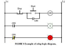
The relay logic circuit forms an electrical schematic diagram for the control of input and output devices.
When designing a system, it was common practice to skip numbers for the rungs to allow later additions as required.
Wire labels were typically pieces of white tape with numbers or letters printed onto them and collected in small, pocket sized booklets.
There are also pocket sized printers that print onto an adhesive backed label that can be wrapped around the wire.
When the START button is pressed, the control relay energizes and its associated contacts change state.
When the STOP button is pressed, the contacts return to their resting state, the red pilot light is ON, and the green switches OFF.
In many cases, it is possible to design a relay logic diagram directly from the narrative description of a control event sequence.
This safety critical application uses interlocking to ensure conflicting routes can never be selected and helps reduce accidents.
Elevators are another common application - large relay logic circuits were employed from the 1930s onward to replace the human elevator operator, but have been progressively superseded with modern solid-state controls in recent years.
Systems using relay logic diagrams in other forms include the Vernam cipher machine, the many 20th century telephone exchanges that controlled their crossbar switches by relays, and the designs for the various electro-mechanical computers including the Harvard Mark II.