Resonant inductive coupling
Resonant inductive coupling is also used in wireless power systems for portable computers, phones, and vehicles.
Various resonant coupling systems in use or are under development for short range (up to 2 meters)[6] wireless electricity systems to power laptops, tablets, smartphones, robot vacuums, implanted medical devices, and vehicles like electric cars, SCMaglev trains[7] and automated guided vehicles.
[8] Specific technologies include: Other applications include: The Tesla coil is a resonant transformer circuit used to generate very high voltages, and is able to provide much higher current than high voltage electrostatic machines such as the Van de Graaff generator.
Resonant transformers are widely used in radio circuits as bandpass filters, and in switching power supplies.
The improved design allowed for the safe production and utilization of high-potential electrical currents, "without serious liability of the destruction of the apparatus itself and danger to persons approaching or handling it."
Today resonant inductive energy transfer is regularly used for providing electric power in many commercially available medical implantable devices.
In addition to buses the use of wireless transfer has been investigated for recharging electric automobiles in parking spots and garages as well.
Current implantable medical and road electrification device designs achieve more than 75% transfer efficiency at an operating distance between the transmit and receive coils of less than 10 cm.
[21] In November 2006, Marin Soljačić and other researchers at the Massachusetts Institute of Technology applied this near field behavior to wireless power transmission, based on strongly-coupled resonators.
[28] Non-resonant coupled inductors, such as typical transformers, work on the principle of a primary coil generating a magnetic field and a secondary coil subtending as much as possible of that field so that the power passing through the secondary is as close as possible to that of the primary.
Over greater distances the non-resonant induction method is highly inefficient and wastes the vast majority of the energy in resistive losses of the primary coil.
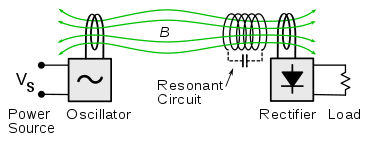
If resonant coupling is used, the secondary coil is capacitive loaded so as to form a tuned LC circuit.
Whether the system can meet the guidelines or the less stringent legal requirements depends on the delivered power and range from the transmitter.
Maximum recommended B-field is a complicated function of frequency, the ICNIRP guidelines for example permit RMS fields of tens of microteslas below 100 kHz, falling with frequency to 200 nanoteslas in the VHF, and lower levels above 400 MHz, where body parts can sustain current loops comparable to a wavelength in diameter, and deep tissue energy absorption reaches a maximum.
A study for the Swedish military found that 85 kHz systems for dynamic wireless power transfer for vehicles can cause electromagnetic interference at a radius of up to 300 kilometers.
[37] When the system is not in the resonance state, this leads to the open-circuit voltage appearing at the secondary being less than predicted by the turns ratio of the coils.
Overcoupling is when the secondary coil is so close and the formation of mutual flux is hindered by the effect of antiresonance, and critical coupling is when the transfer in the passband is optimal.
Generally the voltage gain of non resonantly coupled coils is directly proportional to the square root of the ratio of secondary and primary inductances.
It can be shown that a figure of merit for the efficiency is:[39] Where Q1 and Q2 are the Q factors of the source and receiver coils respectively, and k is the coupling coefficient described above.
Unlike the multiple-layer secondary of a non-resonant transformer, coils for this purpose are often single layer solenoids (to minimise skin effect and give improved Q) in parallel with a suitable capacitor.
In the Litz wire-based resonators, insulation is either absent or low permittivity and low-loss materials such as silk are used to minimise dielectric losses.
To remove energy from the secondary coil, different methods can be used, the AC can be used directly or rectified and a regulator circuit can be used to generate DC voltage.