Helicopter rotor
As it is more efficient at low speeds to accelerate a large amount of air by a small degree than a small amount of air by a large degree,[9][10] a low disk loading (thrust per disc area) greatly increases the aircraft's energy efficiency, and this reduces the fuel use and permits reasonable range.
[10] The blades of a helicopter are long, narrow airfoils with a high aspect ratio, a shape that minimizes drag from tip vortices (see the wings of a glider for comparison).
Rotor blades are made out of various materials, including aluminium, composite structure, and steel or titanium, with abrasion shields along the leading edge.
[15] Tips of some helicopter blades can be specially designed to reduce turbulence and noise and to provide more efficient flying.
This hinge is responsible for the change in pitch of rotor blades excited via pilot input to the collective or cyclic.
Elastomeric bearings are constructed from a rubber type material and provide limited movement that is perfectly suited for helicopter applications.
The flybar has a weight or paddle (or both for added stability on smaller helicopters) at each end to maintain a constant plane of rotation.
Through mechanical linkages, the stable rotation of the bar mixes with the swashplate movement to damp internal (steering) as well as external (wind) forces on the rotor.
Stanley Hiller arrived at a similar method to improve stability by adding short stubby airfoils, or paddles, at each end.
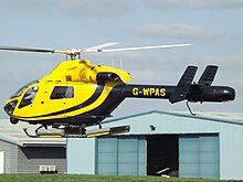
The three most common controls used today are the tail rotor, Eurocopter's Fenestron (also called a fantail), and MD Helicopters' NOTAR.
The housing is integral with the aircraft skin and allows a high rotational speed; therefore, a ducted fan can have a smaller size than a conventional tail rotor.
Besides Eurocopter and its predecessors, a ducted fan tail rotor was also used on the canceled military helicopter project, the United States Army's RAH-66 Comanche, as the FANTAIL.
Although the concept took some time to refine, the NOTAR system is simple in theory and provides antitorque the same way a wing develops lift by using the Coandă effect.
[27] A variable pitch fan is enclosed in the aft fuselage section immediately forward of the tail boom and is driven by the main rotor transmission.
[28] A more heavily modified prototype demonstrator first flew in March 1986 and successfully completed an advanced flight-test program, validating the system for future application in helicopter design.
A predecessor (of sorts) to this system existed in the form of Great Britain's Cierva W.9 helicopter, a late 1940s aircraft using the cooling fan from its piston engine to push air through a nozzle built into the tailboom to counteract rotor-torque.
Though this method is simple and eliminates torque reaction, prototypes that have been built are less fuel efficient than conventional helicopters.
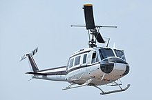
During the Cold War, an American company, Kaman Aircraft, produced the HH-43 Huskie for USAF firefighting and rescue missions.
Center of pressure is the imaginary point on the chord line where the resultant of all aerodynamic forces are considered to be concentrated.
[34] The octocopter configuration is used notably in NASA's planned Dragonfly probe, designed to fly in the atmosphere of Saturn's Moon Titan.
[36] The first aerobatic manned drone, as this type of electrically powered multi-rotor helicopter is known, had 12 rotors and could carry 1-2 people.
In the late 1960s the US Army discovered the danger of a main rotor striking a helicopter's own tail, in certain aerodynamic conditions.
When a helicopter flies low to the ground in desert environments, sand striking the rotor blade can cause erosion.
At night, sand hitting the metal abrasion strip causes a visible corona or halo around the rotor blades.
[51] The philosopher Ge Hong's book the Baopuzi (Master Who Embraces Simplicity), written around 317, describes the apocryphal use of a possible rotor in aircraft: "Some have made flying cars [feiche 飛車] with wood from the inner part of the jujube tree, using ox-leather (straps) fastened to returning blades so as to set the machine in motion.
[51] Sir George Cayley, inspired by the Chinese toy in his childhood, created multiple vertical flight machines with rotors made of tin sheets.
[55] The first successful attempt at a single-lift rotor helicopter design used a four-blade main rotor, as designed by Soviet aeronautical engineers Boris N. Yuriev and Alexei M. Cheremukhin, both working at the Tsentralniy Aerogidrodinamicheskiy Institut (TsAGI, the Central Aerohydrodynamic Institute) near Moscow in the early 1930s.
The Hiller system variant using airfoiled paddles at the flybar's ends has been used in many of the earliest designs of remote control model helicopters, from their 1970s origins onwards to the very early 21st century.
In the late 1940s, the making of helicopter rotor blades was a job that inspired John T. Parsons to be a pioneer of numerical control (NC).
NC and CNC (computerized numerical control) turned out to be an important new technology that later affected all machining industries.