Slowed rotor
In the compound helicopter and related aircraft configurations such as the gyrodyne and winged autogyro, reducing the rotational speed of the rotor and offloading part of its lift to a fixed wing reduces drag, enabling the aircraft to fly faster.
[5] Alternatively, research suggests that twin-engine helicopters may decrease fuel consumption by 25%-40% when running only one engine, given adequate height and velocity well inside the safe areas of the height–velocity diagram.
[10] Varying the rotor speed may induce severe vibrations at specific resonance frequencies.
[12][1] The X2 deals with the compressibility issue by reducing its rotor speed[1] from 446 to 360 RPM[13][14] to keep the advancing blade tip below the sound barrier when going above 200 knots.
[15] The rotors of conventional helicopters are designed to operate at a fixed speed of rotation, to within a few percent.
[1][26][29][30] At the extreme, the theoretical top speed for a rotary winged aircraft is about 225 knots (259 mph; 417 km/h),[28] just above the current official speed record for a conventional helicopter held by a Westland Lynx, which flew at 400 km/h (250 mph) in 1986[31] where its blade tips were nearly Mach 1.
[33][34][35] Upper mu limit is a critical design factor for rotorcraft,[23] and the optimum for traditional helicopters is around 0.4.
[43][44] The region of reverse flow on the retreating blade is not well understood,[45][46] however some research has been conducted,[47][48] particularly for scaled rotors.
[49][50] The US Army Aviation Applied Technology Directorate runs a supporting program in 2016 aiming at developing transmissions with a 50% rotor speed reduction.
[55] Conventional helicopters have constant-speed rotors and adjust lift by varying the blade angle of attack or collective pitch.
[52][53] Reducing the rotational speed and increasing the angle of attack can therefore give a significant reduction in rotor drag, allowing lower fuel consumption.
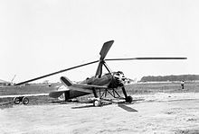
[5] Technical parameters given for each type listed: When Juan de la Cierva developed the autogyro through the 1920s and 1930s, it was found that the tip speeds of the advancing rotor blade could become excessive.
Designers such as he and Harold F. Pitcairn developed the idea of adding a conventional wing to offload the rotor during high-speed flight, allowing it to rotate at slower speeds.
[citation needed] The 1932 Pitcairn PCA-2 autogyro had a maximum speed of 20-102 knots (117 mph; 189 km/h),[56] μ of 0.7,[57] and L/D of 4.8[58] NACA engineer John Wheatley examined the effect of varying advance ratios up to about 0.7 in a wind tunnel in 1933 and published a landmark study in 1934.
Although lift could be predicted with some accuracy, by 1939 the state of the art theory still gave unrealistically low values for rotor drag.
[59] Fairey Aviation in the UK worked on gyrodynes in the late 1940s and 1950s developing tip-jet propulsion which eliminated the need for countertorque.
Stub wings and a thrust turbojet to offload the rotor were first added to an XH-51A and in 1965 this allowed the craft to achieve a world speed record of 272 miles per hour (438 km/h).
[83][84] The compound autogyro, in which the rotor is supplemented by wings and thrust engine but is not itself powered, has also undergone further refinement by Jay Carter Jr.
[87] The potential of the slowed rotor in enhancing fuel economy has also been studied in the Boeing A160 Hummingbird UAV, a conventional helicopter.