Solenoid valve
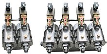
Solenoids offer fast and safe switching, high-reliability, long service life, good medium compatibility of the materials used, low control power and compact design.
If the force required is low enough, the solenoid is able to directly actuate the main valve.
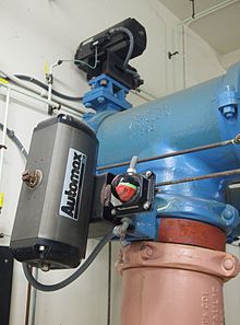
[4] If fluid pressures are high and orifice diameter is large, a solenoid may not generate enough force on its own to actuate the valve.
These valves are used in dishwashers, irrigation systems, and other applications where large pressures and/or volumes are desired.
Pilot-operated valves are slightly slower; depending on their size, typical values range from 15 to 150 milliseconds.
[2] Power consumption and supply requirements of the solenoid vary with application, being primarily determined by fluid pressure and orifice diameter.
For example, a popular 3⁄4-inch 150 psi sprinkler valve, intended for 24 VAC (50–60 Hz) residential systems, has a momentary inrush of 7.2 VA, and a holding power requirement of 4.6 VA.[5] Comparatively, an industrial 1⁄2-inch 10,000 psi valve, intended for 12, 24, or 120 VAC systems in high-pressure fluid and cryogenic applications, has an inrush of 300 VA and a holding power of 22 VA.[6] Neither valve lists a minimum pressure required to remain closed in the unpowered state.
While there are multiple design variants, the following is a detailed breakdown of a typical pilot-operated solenoid valve.
The diagram to the right shows the design of a basic valve, controlling the flow of water in this example.
The diaphragm has a pinhole through its center which allows a very small amount of water to flow through.
This water fills cavity C so that pressure is roughly equal on both sides of the diaphragm.
Diaphragm B will stay closed as long as small drain passage D remains blocked by a pin, which is controlled by solenoid E. In a normally closed valve, supplying an electric current to the solenoid will raise the pin via magnetic force, and the water in cavity C drains out through passage D faster than the pinhole can refill it.
This is why pilot-operated valves will not work without a sufficient pressure differential between input and output, the "muscle" needs to be strong enough to push back against the diaphragm and open it.
If the core tube were magnetic, then it would offer a shunt path for the field lines.
[11] In some designs, the core tube is an enclosed metal shell produced by deep drawing.
Such a design simplifies the sealing problems because the fluid cannot escape from the enclosure, but the design also increases the magnetic path resistance because the magnetic path must traverse the thickness of the core tube twice: once near the plugnut and once near the core.
The valve body must be compatible with the fluid; common materials are brass, stainless steel, aluminum, and plastic.
To simplify the sealing issues, the plugnut, core, springs, shading ring, and other components are often exposed to the fluid, so they must be compatible as well.
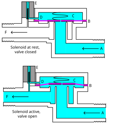
B- Diaphragm
C- Pressure chamber
D- Pressure relief passage
E- Electro Mechanical Solenoid
F- Output side
