Transmission line
In electrical engineering, a transmission line is a specialized cable or other structure designed to conduct electromagnetic waves in a contained manner.
Transmission lines are used for purposes such as connecting radio transmitters and receivers with their antennas (they are then called feed lines or feeders), distributing cable television signals, trunklines routing calls between telephone switching centres, computer network connections and high speed computer data buses.
Ordinary electrical cables suffice to carry low frequency alternating current (AC), such as mains power, which reverses direction 100 to 120 times per second, and audio signals.
Transmission lines use specialized construction, and impedance matching, to carry electromagnetic signals with minimal reflections and power losses.
At frequencies of microwave and higher, power losses in transmission lines become excessive, and waveguides are used instead,[1] which function as "pipes" to confine and guide the electromagnetic waves.
Mathematical analysis of the behaviour of electrical transmission lines grew out of the work of James Clerk Maxwell, Lord Kelvin, and Oliver Heaviside.
In 1885, Heaviside published the first papers that described his analysis of propagation in cables and the modern form of the telegrapher's equations.
[7] For the purposes of analysis, an electrical transmission line can be modelled as a two-port network (also called a quadripole), as follows: In the simplest case, the network is assumed to be linear (i.e. the complex voltage across either port is proportional to the complex current flowing into it when there are no reflections), and the two ports are assumed to be interchangeable.
They were developed by Oliver Heaviside who created the transmission line model, and are based on Maxwell's equations.
The physical significance of this is that electromagnetic waves propagate down transmission lines and in general, there is a reflected component that interferes with the original signal.
They are also wave equations, and have solutions similar to the special case, but which are a mixture of sines and cosines with exponential decay factors.
Alternatively, the complex square root can be evaluated algebraically, to yield: and with the plus or minus signs chosen opposite to the direction of the wave's motion through the conducting medium.
If R, G, L, and C are constants that are not frequency dependent and the Heaviside condition is met, then waves travel down the transmission line without dispersion distortion.
where n is an integer (meaning that the length of the line is a multiple of half a wavelength), the expression reduces to the load impedance so that for all
), the input impedance is purely imaginary and a periodic function of position and wavelength (frequency) For the case of an open load (i.e.
Scattering (S) matrix parameters model the electrical behavior of the transmission line with matched loads at each termination.
[10] For lossless and lossy transmission lines respectively, the S parameter matrix is as follows,[13][14] using standard hyperbolic to circular complex translations.
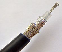
Coaxial lines can therefore be bent and twisted (subject to limits) without negative effects, and they can be strapped to conductive supports without inducing unwanted currents in them.
However, at frequencies for which the wavelength (in the dielectric) is significantly shorter than the circumference of the cable other transverse modes can propagate.
A stripline circuit uses a flat strip of metal which is sandwiched between two parallel ground planes.
[22] The format is also used for data network distribution inside buildings, but the cable is more expensive because the transmission line parameters are tightly controlled.
When used for a single, balanced line, magnetic interference picked up by the cable arrives as a virtually perfect common mode signal, which is easily removed by coupling transformers.
[23][24] The disadvantage is that star quad, in combining two conductors, typically has double the capacitance of similar two-conductor twisted and shielded audio cable.
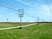
Lecher lines are a form of parallel conductor that can be used at UHF for creating resonant circuits.
Electrical transmission lines are very widely used to transmit high frequency signals over long or short distances with minimum power loss.
It can be considered as multiple transmission line segments connected in series, with the characteristic impedance of each individual element to be
At higher frequencies, the reactive parasitic effects of real world lumped elements, including inductors and capacitors, limits their usefulness.
[29][30] More accurate forms of multimode high frequency inductor modeling with transmission lines exist for advanced designers.
One method recommended in the RSGB's radiocommunication handbook is to take an open-circuited length of transmission line wired in parallel with the feeder delivering signals from an aerial.
By cutting the free end of the transmission line, a minimum in the strength of the signal observed at a receiver can be found.