Valve RF amplifier
Low to medium power valve amplifiers for frequencies below the microwaves were largely replaced by solid state amplifiers during the 1960s and 1970s, initially for receivers and low power stages of transmitters, transmitter output stages switching to transistors somewhat later.
[1][citation needed] Valves are high voltage / low current devices in comparison with transistors.
Thus while solid state high power short wave transmitters are technically possible, economic considerations still favor valves above 3 MHz and 10,000 watts.
They use an iron core transformer to provide a suitable high impedance load to the valve(s) while driving a speaker, which is typically 8 Ohms.
[citation needed] The most efficient valve-based RF amplifiers operate class C. If used with no tuned circuit in the output, this would distort the input signal, producing harmonics.
However, class C amplifiers normally use a high Q output network which removes the harmonics, leaving an undistorted sine wave identical to the input waveform.
The development of FM broadcasting improved fidelity by using a greater bandwidth which was available in the VHF range, and where atmospheric noise was absent.
Today's digital radio that carries coded data over various phase modulations (such as GMSK, QPSK, etc.)
Today's cellular radio and digital broadcast standards are extremely demanding in terms of the spectral envelope and out of band emissions that are acceptable (in the case of GSM for example, −70 dB or better just a few hundred kilohertz from center frequency).
Later beam power tubes such as the 807 and (direct heated) 813 were also used in large numbers in (especially military) radio transmitters.
Depending on the application, a fair number of radio frequency amplifiers continue to have valve construction, due to their simplicity, where as, it takes several output transistors with complex splitting and combining circuits to equal the same amount of output power of a single valve.
Solid state devices have a very low output impedance which allows matching via a broadband transformer covering a large range of frequencies, for example 1.8 to 30 MHz.
While the proper low pass filter must be switch selected for the frequency range of interest, the result is considered to be a "no tune" design.
Valve amplifiers have a tuned network that serves as both the low pass harmonic filter and impedance matching to the output load.
In either case, both solid state and valve devices need such filtering networks before the RF signal is output to the load.
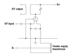
In common with all three basic designs shown here, the anode of the valve is connected to a resonant LC circuit which has another inductive link which allows the RF signal to be passed to the output.
The circuit shown has been largely replaced by a Pi network which allows simpler adjustment and adds low pass filtering.
A DC bias is applied to the valve to ensure that the part of the transfer equation which is most suitable to the required application is used.
In the RF designs shown on this page, a tuned circuit is between the anode and the high voltage supply.
This tuned circuit is brought to resonance presenting an inductive load that is well matched to the valve and thus results in an efficient power transfer.
Valves that require a negative grid bias can be used by putting a positive DC voltage on the cathode.
Various methods exist for introducing an out-of-phase signal from the output back to the input so that the effect is cancelled.
Transit time effects are important at these frequencies, so feedback is not normally usable and for performance critical applications alternative linearisation techniques have to be used such as degeneration and feedforward.
Even with a hypothetical perfect amplifier, however, noise is unavoidably present due to thermal fluctuations in the signal source (usually assumed to be at room temperature, T = 295 K).
For the EF86 tube, for example, this voltage noise is specified (see e.g., the Valvo, Telefunken or Philips data sheets) as 2 microvolts integrated over a frequency range of approximately 25 Hz to 10 kHz.
It can be reduced by choosing very pure materials for the cathode nickel, and running the tube at an optimized (generally low) anode current.
At radio frequencies, things are more complicated: (i) The input impedance of a tube has a real component that goes down like 1/f² (due to cathode lead inductance and transit time effects).
This means the input impedance can no longer be increased arbitrarily in order to reduce the noise figure.
Planar triodes are better, but very early, transistors have reached noise figures substantially lower than tubes at UHF.
Valves continue to be used in some high-power, high-frequency amplifiers used for short wave broadcasting, VHF and UHF TV and (VHF) FM radio, also in existing "radar, countermeasures equipment, or communications equipment"[7] using specially designed valves, such as the klystron, gyrotron, traveling-wave tube, and crossed-field amplifier; however, new designs for such products are now invariably semiconductor-based.