Wingtip device
[1] Although there are several types of wing tip devices which function in different manners, their intended effect is always to reduce an aircraft's drag.
[1] U.S. Air Force studies indicate that a given improvement in fuel efficiency correlates directly with the causal increase in the aircraft's lift-to-drag ratio.
[2] The initial concept dates back to 1897, when English engineer Frederick W. Lanchester patented wing end-plates as a method for controlling wingtip vortices.
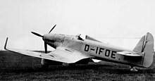
This was the so-called "Lippisch-Ohren" (Lippisch-ears), allegedly attributed to the Messerschmitt Me 163's designer Alexander Lippisch, and first added to the M3 and M4 third and fourth prototypes of the Heinkel He 162A Spatz jet light fighter for evaluation.
This addition was done in order to counteract the dutch roll characteristic present in the original He 162 design, related to its wings having a marked dihedral angle.
This became a standard feature of the approximately 320 completed He 162A jet fighters built, with hundreds more He 162A airframes going unfinished by V-E Day.
[9] The term "winglet" was previously used to describe an additional lifting surface on an aircraft, like a short section between wheels on fixed undercarriage.
Richard Whitcomb's research in the 1970s at NASA first used winglet with its modern meaning referring to near-vertical extension of the wing tips.
The wingtip vortex, which rotates around from below the wing, strikes the cambered surface of the winglet, generating a force that angles inward and slightly forward, analogous to a sailboat sailing close hauled.
This small contribution can be worthwhile over the aircraft's lifetime, provided the benefit offsets the cost of installing and maintaining the winglets.
[15] Richard T. Whitcomb, an engineer at NASA's Langley Research Center, further developed Hoerner's concept in response to the sharp increase in the cost of fuel after the 1973 oil crisis.
With careful aeronautical design he showed that, for a given bending moment, a near-vertical winglet offers a greater drag reduction compared to a horizontal span extension.
[16] Whitcomb's designs were flight-tested in 1979–80 by a joint NASA/Air Force team, using a KC-135 Stratotanker based at the Dryden Flight Research Center.
Winglets are also applied to other business aircraft, reducing take-off distance to operate from smaller airports, and allowing higher cruise altitudes.
[20] The average commercial jet sees a 4-6 percent increase in fuel efficiency and as much as a 6% decrease in in-flight noise from the use of winglets.
Actual fuel savings and the related carbon output can vary significantly by plane, route and flight conditions.
Boeing announced a new version of the 747, the 747-400, in 1985, with an extended range and capacity, using a combination of winglets and increased span to carry the additional load.
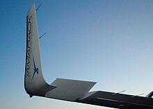
A blended winglet is attached to the wing with a smooth curve instead of a sharp angle and is intended to reduce interference drag at the wing/winglet junction.
A sharp interior angle in this region can interact with the boundary layer flow causing a drag inducing vortex, negating some of the benefit of the winglet.
[23] The Aviation Partners/Boeing 8 ft (2.4 m) extensions decrease fuel consumption by 4% for long-range flights and increase range by 130 or 200 nmi (240 or 370 km) for the 737-800 or the derivative Boeing Business Jet as standard.
[25] In 2009 Airbus launched its "Sharklet" blended winglet, designed to enhance the payload-range of its A320 family and reduce fuel burn by up to 4% over longer sectors.
Like winglets, they increase the effective wing aspect ratio and diminish wingtip vortices, decreasing lift-induced drag.
[31] Raked wingtips offer several weight-reduction advantages relative to simply extending the conventional main wingspan.
Additionally, the leading-edge sweep results in the center of pressure being located farther aft than for simple extensions of the span of conventional main wings.
At high load factors, this relative aft location of the center of pressure causes the raked wingtip to be twisted more leading-edge down, reducing the bending moment on the inboard wing.
For the 737 Next Generation, third-party vendor Aviation Partners has introduced a similar design to the 737 MAX wingtip device known as the split scimitar winglet,[34] with United Airlines as the launch customer.
Others had attempted to apply Whitcomb's winglets to gliders before, and they did improve climb performance, but this did not offset the parasitic drag penalty in high-speed cruise.
Non-planar wingtips provide the wake control benefit of winglets, with less parasitic drag penalty, if designed carefully.
[42] The system uses Tamarack Active Camber Surfaces (TACS) to aerodynamically "switch off" the effects of the wingtip device when the aircraft is experiencing high-g events such as large gusts or severe pull-ups.
[51] Another application of the same principle was introduced to the keel of the "America's Cup"- winning Australian yacht Australia II of 1982, designed by Ben Lexcen.