XOR gate
XOR gate (sometimes EOR, or EXOR and pronounced as Exclusive OR) is a digital logic gate that gives a true (1 or HIGH) output when the number of true inputs is odd.
Hence it functions as a inverter (a NOT gate) which may be activated or deactivated by a switch.
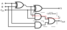
As a result, XOR gates are used to implement binary addition in computers.
The logic symbols ⊕, Jpq, and ⊻ can be used to denote an XOR operation in algebraic expressions.
C-like languages use the caret symbol ^ to denote bitwise XOR.
(Note that the caret does not denote logical conjunction (AND) in these languages, despite the similarity of symbol.)
The XOR gate is most commonly implemented using MOSFETs circuits.
[4] The metal–oxide–semiconductor (CMOS) implementations of the XOR gate corresponding to the AOI logic above are shown below.
On the left, the nMOS and pMOS transistors are arranged so that the input pairs
activate each one of the two nMOS paths in the bottom to Vss for a logic low.
The AOI implementation without inverted input has been used, for example, in the Intel 386 CPU.
This implementation uses two Transmission gates and two inverters not shown in the diagram to generate
[7] The trade-off with the previous implementation is that since transmission gates are not ideal switches, there is resistance associated with them, so depending on the signal strength of the input, cascading them may degrade the output levels.
and the bottom pass-gate with just two transistors arranged like an inverter but with the source of the pMOS connected to
The two in the middle are a transmission gate that drives the output to the value of A when B is at a logic low and the two rightmost transistors form an inverter needed to generate
As alternative, if different gates are available we can apply Boolean algebra to transform
as stated above, and apply de Morgan's Law to the last term to get
An alternative arrangement is of five NOR gates in a topology that emphasizes the construction of the function from
Another alternative arrangement is of five NAND gates in a topology that emphasizes the construction of the function from
For the NAND constructions, the upper arrangement requires fewer gates.
The most common standard chip codes are: Literal interpretation of the name "exclusive or", or observation of the IEC rectangular symbol, raises the question of correct behaviour with additional inputs.
For example, the 74LVC1G386 microchip is advertised as a three-input logic gate, and implements a parity generator.
For example, if we add 1 plus 1 in binary, we expect a two-bit answer, 10 (i.e. 2 in decimal).
A slightly larger Full Adder circuit may be chained together in order to add longer binary numbers.
Pseudo-random number (PRN) generators, specifically linear-feedback shift registers (LFSR), are defined in terms of the exclusive-or operation.
Hence, a suitable setup of XOR gates can model a linear-feedback shift register, in order to generate random numbers.
[15]: 425 An XOR gate may be used to easily change between buffering or inverting a signal.
Correlators are used in many communications devices such as CDMA receivers and decoders for error correction and channel codes.
A correlator looking for 11010 in the data sequence 1110100101 would compare the incoming data bits against the target sequence at every possible offset while counting the number of matches (zeros): In this example, the best match occurs when the target sequence is offset by 1 bit and all five bits match.
By looking at the difference between the number of ones and zeros that come out of the bank of XOR gates, it is easy to see where the sequence occurs and whether or not it is inverted.