Yaw bearing
The yaw bearing must cope with enormous static and dynamic loads and moments during the wind turbine operation, and provide smooth rotation characteristics for the orientation of the nacelle under all weather conditions.
Windmills of the 18th century began implementing rotatable nacelles to capture wind coming from different directions.
The yaw systems of these "primitive" windmills were surprisingly similar to the ones on modern wind turbines.
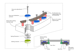
This system comprises multiple removable radial gliding pads in combination with an axial roller bearing.
In this case half of the yaw drives apply a small amount of torque for clockwise rotation and the other half apply torque in the opposite direction and then activate the internal magnetic brakes of the electric motor.
Contrary to the old windmill concept, the modern yaw bearings support the nacelle also from the top[clarification needed] thus restraining the nacelle from being rotated by the Y-axis due to the moments induced by the upper half of the rotor sweep disk and the X-axis due to the torque of the drive train (i.e. rotor, shaft, generator, etc.
These gliding pads come in sliding contact with a steel disk, which is usually equipped with gear teeth to form a gliding-disk/gear-rim.
In its simplest form, the gliding yaw bearing uses pads (usually made out of polymers) distributed around the three contact surfaces to provide a proper guiding system for the radial and axial movement with relatively low friction coefficient.
Such systems are economical and very robust but do not allow individual adjustment of the axial and radial gliding elements.
This is usually the top axial surface of the gliding bearing, which constantly supports the weight of the whole nacelle-rotor assembly.
An alternative solution to this problem is the use of mechanical or hydraulic jacks able to partially or fully lift the nacelle-rotor assembly while the gliding yaw bearing is still in place.
This is necessary in order to avoid un-even wear of the gliding pads and excessive loading on some sectors of the yaw bearing.