3D projection
The result is a graphic that contains conceptual properties to interpret the figure or image as not actually flat (2D), but rather, as a solid object (3D) being viewed on a 2D display.
Projections can be calculated through employment of mathematical analysis and formulae, or by using various geometric and optical techniques.
[further explanation needed] Methods provide a uniform imaging procedure among people trained in technical graphics (mechanical drawing, computer aided design, etc.).
By following a method, the technician may produce the envisioned picture on a planar surface such as drawing paper.
Images drawn in parallel projection rely upon the technique of axonometry ("to measure along axes"), as described in Pohlke's theorem.
Axonometry should not be confused with axonometric projection, as in English literature the latter usually refers only to a specific class of pictorials (see below).
The orthographic projection is derived from the principles of descriptive geometry and is a two-dimensional representation of a three-dimensional object.
If the normal of the viewing plane (the camera direction) is parallel to one of the primary axes (which is the x, y, or z axis), the mathematical transformation is as follows; To project the 3D point
In particular, parallel lengths at all points in an orthographically projected image are of the same scale regardless of whether they are far away or near to the virtual viewer.
Although six different sides can be drawn, usually three views of a drawing give enough information to make a 3D object.
Because of its simplicity, oblique projection is used exclusively for pictorial purposes rather than for formal, working drawings.
In an oblique pictorial drawing, the displayed angles among the axes as well as the foreshortening factors (scale) are arbitrary.
On the flat drawing, two axes, x and z on the figure, are perpendicular and the length on these axes are drawn with a 1:1 scale; it is thus similar to the dimetric projections, although it is not an axonometric projection, as the third axis, here y, is drawn in diagonal, making an arbitrary angle with the x″ axis, usually 30 or 45°.
The distortion caused by foreshortening is uniform, therefore the proportionality of all sides and lengths are preserved, and the axes share a common scale.
In dimetric pictorials (for methods, see Dimetric projection), the direction of viewing is such that two of the three axes of space appear equally foreshortened, of which the attendant scale and angles of presentation are determined according to the angle of viewing; the scale of the third direction (vertical) is determined separately.
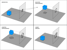
Objects drawn with parallel projection do not appear larger or smaller as they extend closer to or away from the viewer.
While advantageous for architectural drawings, where measurements must be taken directly from the image, the result is a perceived distortion, since unlike perspective projection, this is not how our eyes or photography normally work.
It also can easily result in situations where depth and altitude are difficult to gauge, as is shown in the illustration to the right.
However, this difference in elevation is not apparent if one covers the right half of the picture, as the boxes (which serve as clues suggesting height) are then obscured.
M. C. Escher's Waterfall (1961), while not strictly utilizing parallel projection, is a well-known example, in which a channel of water seems to travel unaided along a downward path, only to then paradoxically fall once again as it returns to its source.
An extreme example is depicted in the film Inception, where by a forced perspective trick an immobile stairway changes its connectivity.
The video game Fez uses tricks of perspective to determine where a player can and cannot move in a puzzle-like fashion.
It also means that lines which are parallel in nature (that is, meet at the point at infinity) appear to intersect in the projected image.
They are useful for drawing chessboard floors which, in turn, serve for locating the base of objects on the scene.
Natural heights are measured above the ground line and then projected in the same way until they meet the vertical from the map.
The camera's position, orientation, and field of view control the behavior of the projection transformation.
The following variables are defined to describe this transformation: Most conventions use positive z values (the plane being in front of the pinhole
):[clarification needed] This transformed point can then be projected onto the 2D plane using the formula (here, x/y is used as the projection plane; literature also may use x/z):[11] Or, in matrix form using homogeneous coordinates, the system in conjunction with an argument using similar triangles, leads to division by the homogeneous coordinate, giving The distance of the viewer from the display surface,
(Note: This assumes that you map the points (-1,-1) and (1,1) to the corners of your viewing surface) The above equations can also be rewritten as: In which
multiply the point coordinates by: where Because the camera is in 3D, the same works for the screen y-coordinate, substituting y for x in the above diagram and equation.