555 timer IC
In 2017, it was said that over a billion 555 timers are produced annually by some estimates, and that the design was "probably the most popular integrated circuit ever made".
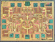
[5] The timer IC was designed in 1971 by Hans Camenzind under contract to Signetics.
[3] In 1968, he was hired by Signetics to develop a phase-locked loop (PLL) IC.
He designed an oscillator for PLLs such that the frequency did not depend on the power supply voltage or temperature.
Signetics subsequently laid off half of its employees due to the 1970 recession, and development on the PLL was thus frozen.
[8] After this design was tested and found to be without errors, Camenzind got the idea of using a direct resistance instead of a constant current source, finding that it worked satisfactorily.
[8] This revised version passed a second design review, and the prototypes were completed in October 1971 as the NE555V (plastic DIP) and SE555T (metal TO-5).
For months I was inundated by phone calls from engineers who had new ideas for using the device.
"[8] Several books report the name "555" timer IC derived from the three 5 kΩ resistors inside the chip.
[10][11][12] However, in a recorded interview with an online transistor museum curator,[13] Hans Camenzind said "It was just arbitrarily chosen.
It was Art Fury (marketing manager) who thought the circuit was gonna sell big who picked the name '555' timer IC.
[2] The 555 IC has the following operating modes: In the astable configuration, the 555 timer puts out a continuous stream of rectangular pulses having a specific period.
requirements: To create an output high time shorter than the low time (i.e., a duty cycle less than 50%) a fast diode (i.e. 1N4148 signal diode) can be placed in parallel with R2, with the cathode on the capacitor side.
But the diode's forward voltage drop Vdiode slows charging on the capacitor, so the high time is longer than the often-cited
When Vdiode is small relative to Vcc, this charging is faster and approaches
At the other extreme, when Vcc = 15 V, and Vdiode = 0.3 V, the high time is 0.725 R1C, which is closer to the expected 0.693 R1C.
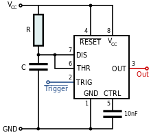
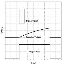
Monostable mode produces an output pulse when the trigger signals drops below 1⁄3 VCC.
An RC circuit sets the output pulse's duration as the time
[b] The output pulse duration can be lengthened or shortened as desired by adjusting the values of R and C. Subsequent triggering before the end of this timing interval won't affect the output pulse.
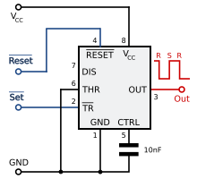
[26] The trigger and reset inputs may be held high via pull-up resistors if they are normally Hi-Z and only enabled by connecting to ground.
For the schematic on the right, an input signal is AC-coupled through a low value series capacitor, then biased by identical high-resistance resistors
This centered signal is connected to both the trigger and threshold input pins of the timer.
The input signal must be strong enough to excite the trigger levels of the comparators to exceed the lower 1⁄3 VCC and upper 2⁄3 VCC thresholds in order to cause them to change state, thus providing the Schmitt trigger feature.
[1] The MIC1555 is a CMOS 555-type timer with three fewer pins available in SOT23-5 (0.95 mm pitch) surface-mount package.
Other 555 timers can have different specifications depending on the grade (industrial, military, medical, etc.).
Numerous companies have manufactured one or more variants of the 555, 556, 558 timers over the past decades, under many different part numbers.
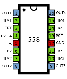
[17][39][38] The quad version is called 558 and has four reduced-functionality timers in a 16-pin package designed primarily for monostable multivibrator applications.