Acoustic transmission line
Technically it is the acoustic analog of the electrical transmission line, typically conceived as a rigid-walled duct or tube, that is long and thin relative to the wavelength of sound present in it.
Examples of transmission line (TL) related technologies include the (mostly obsolete) speaking tube, which transmitted sound to a different location with minimal loss and distortion, wind instruments such as the pipe organ, woodwind and brass which can be modeled in part as transmission lines (although their design also involves generating sound, controlling its timbre, and coupling it efficiently to the open air), and transmission line based loudspeakers which use the same principle to produce accurate extended low bass frequencies and avoid distortion.
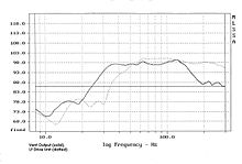
Phase inversion is achieved by selecting a length of line that is equal to the quarter wavelength of the target lowest frequency.
Because the line is operating over several octaves with the drive unit, cone excursion is reduced, providing higher SPL's and lower distortion levels, compared with reflex and infinite baffle designs.
The complex loading of the bass drive unit demands specific Thiele-Small driver parameters to realise the full benefits of a TL design.
However, most drive units in the marketplace are developed for the more common reflex and infinite baffle designs and are usually not suitable for TL loading.
High efficiency bass drivers with extended low frequency ability, are usually designed to be extremely light and flexible, having very compliant suspensions.
High-specification acoustic foams, developed by loudspeaker manufacturers such as PMC, with similar characteristics to longhaired wool, provide repeatable results for consistent production.
A pipe of sufficient length could be tapered, and stuffed so that the energy loss was almost complete, minimizing output from the open end.
In 1965, A R Bailey's article in Wireless World, “A Non-resonant Loudspeaker Enclosure Design”,[4] detailed a working Transmission Line, which was commercialized by John Wright and partners under the brand name IMF and later TDL, and were sold by audiophile Irving M. "Bud" Fried in the United States.
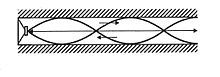
There are many ways in which the duct can be folded and the line is often tapered in cross section to avoid parallel internal surfaces that encourage standing waves.
Depending upon the drive unit and quantity – and various physical properties – of absorbent material, the amount of taper will be adjusted during the design process to tune the duct to remove irregularities in its response.
The inside faces of the duct or line, are treated with an absorbent material to provide the correct termination with frequency to load the drive unit as a TL.