Strike and dip
[1] They are used together to measure and document a structure's characteristics for study or for use on a geologic map.
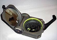
A clinometer measures the feature's dip by recording the inclination perpendicular to the strike.
Any planar feature can be described by strike and dip, including sedimentary bedding, fractures, faults, joints, cuestas, igneous dikes and sills, metamorphic foliation and fabric, etc.
Observations about a structure's orientation can lead to inferences about certain parts of an area's history, such as movement, deformation, or tectonic activity.
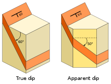
[3] When measuring or describing the attitude of an inclined feature, two quantities are needed.
[5] This can be represented by either a quadrant compass bearing (such as N25°E), or as a single three-digit number in terms of the angle from true north (for example, N25°E would simply become 025 or 025°).
[3][7] A linear feature which lies within a plane can also be measured by its rake (or pitch).
Unlike plunge, which is the feature's azimuth, the rake is the angle measured within the plane from the strike line.
Strike and dip information recorded on a map can be used to reconstruct various structures, determine the orientation of subsurface features, or detect the presence of anticline or syncline folds.
The general alphabetical dip direction (N, SE, etc) can be added to reduce ambiguity.
These apps can make use of the phone's internal accelerometer to provide orientation measurements.
Combined with the GPS functionality of such devices, this allows readings to be recorded and later downloaded onto a map.
A dipmeter is a tool that is lowered into a borehole, and has arms radially attached which can detect the microresistivity of the rock.
By recording the times at which the rock's properties change across each of the sensors, the strike and dip of subsurface features can be worked out.