Antenna measurement
Typical antenna parameters are gain, bandwidth, radiation pattern, beamwidth, polarization, impedance; These are imperative communicative means.
Due to the size required to create a far-field range for large antennas, near-field techniques were developed, which allow the measurement of the field on a distance close to the antenna (typically 3 to 10 times its wavelength).
A third common method is the compact range, which uses a reflector to create a field near the AUT that looks approximately like a plane-wave.
The probe moves in the Cartesian coordinate system and its linear movement creates a regular rectangular sampling grid with a maximum near-field sample spacing of Δx = Δy = λ /2.
Spherical harmonics are used transform these measurements to the far-field The formula for electromagnetic radiation dispersion and information propagation is: where D represents distance, P power and S speed.
The equation means that double the communication distance requires four times the power.
Of course, in the real world there are all sorts of other phenomena which complicate the estimated delivered power, such as Fresnel canceling, path loss, background noise, etc.
A Compact Antenna Test Range (CATR) is a facility which is used to provide convenient testing of antenna systems at frequencies where obtaining far-field spacing to the AUT would be infeasible using traditional free space methods.
One typical embodiment uses a horn feed antenna and a parabolic reflector to accomplish this.
The size of the range that is required can be much less than the size required for a full-size far-field anechoic chamber, although the cost of fabrication of the specially-designed CATR reflector can be expensive due to the need to ensure precision of the reflecting surface (typically less than 1/100λ RMS surface accuracy) and to specially treat the edge of the reflector to avoid diffracted waves which can interfere with the desired beam pattern.
In a slanted range, the receive antenna is mounted higher above ground than the AUT is, either by having the earth surface of the range sloping downward from the AUT mount, or by placing the receive antenna on a much higher mast.
The sloping earth (either actual or effective) serves as a means to eliminate or reduce interference from symmetrical wave reflection, by angling the reflected waves to bounce underneath the receive antenna.
In theory, the same technique could be applied in reverse, to bounce most of the earth-reflected waves above the receive antenna.
The radiation pattern is a graphical depiction of the relative field strength transmitted from or received by the antenna.
Radiation pattern of an antenna can be defined as the locus of all points where the emitted power per unit surface is the same.
The radiated power per unit surface is proportional to the squared electrical field of the electromagnetic wave.
The shape of curves can be very different in Cartesian or polar coordinates and with the choice of the limits of the logarithmic scale.
Loss resistance is the result of power lost to heat in the antenna materials, rather than to coherent radio waves, thus reducing efficiency.
) divided by total resistance (real part of the impedance measured at the voltage node, which is often the feed-point): IEEE defines bandwidth as "The range of frequencies within which the performance of the antenna, with respect to some characteristic, conforms to a specified standard.
High-gain antennas have the advantage of longer range and better signal quality, but must be aimed carefully in a particular direction.
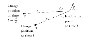
is where: The "prime" in this formula appears because the electromagnetic signal travels at the speed of light.
We will see their current position years in the future; some of the stars that we see today no longer exist.
However, if the distance is large enough, the first two terms become negligible and only the third remains: If the charge q is in sinusoidal motion, meaning that it is being accelerated, with amplitude
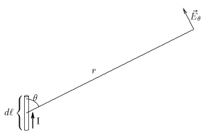
is The left side of this equation is the electrical field of the electromagnetic wave radiated by a small length of conductor.
The electrical field and the radiated power are maximal in the plane perpendicular to the current element.
Only the real part is physically meaningful: where: The (small) electric field of the electromagnetic wave radiated by an element of current is: And for the time
This addition is complicated by the fact that the direction and phase of each of the electric fields are, in general, different.
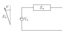
However, using the reciprocity theorem, it is possible to prove that the Thévenin equivalent circuit of a receiving antenna is:
From this formula, it is easy to prove the following definitions: is the length which, multiplied by the electrical field of the received wave, give the voltage of the Thévenin equivalent antenna circuit.
This also implies that under matched conditions, the amount of power re-radiated by the receiving antenna is equal to that absorbed.