Axial turbine
A set of static guide vanes or nozzle vanes accelerates and adds swirl to the fluid and directs it to the next row of turbine blades mounted on a turbine rotor.
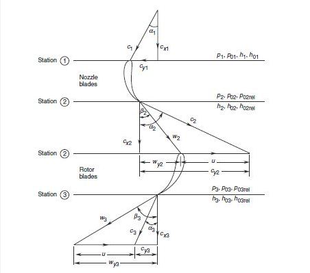
Axial and tangential components of both absolute and relative velocities are shown in the figure.
Static and stagnation values of pressure and enthalpy in the absolute and relative systems are also shown.
The absolute velocity of the fluid increases corresponding to the pressure drop through the nozzle blade row in which the only transformation of energy occurs.
In the absence of any pressure drop through the rotor blades, the relative velocities at their entry and exit are the same for frictionless flow.
A single-stage utilizing a large pressure drop will have an impractically high peripheral speed of its rotor.
One of the methods to employ multi-stage expansion in impulse turbines is to generate high-velocity of the fluid by causing it to expand through a large pressure drop in the nozzle blade row.
The decrease in the absolute velocity of the fluid across the two rotor blade rows (R1 and R2) is due to the energy transfer; the slight decrease in the fluid velocity through the fixed guide blades (F) is due to losses.
Since the turbine is of the impulse type, the pressure of the fluid remains constant after its expansion in the nozzle blade row.
On account of the comparatively lower pressure drop, the nozzle blade rows are subsonic (M < 1).
This gives a turbine of shorter length as compared to the reaction type, with a penalty on efficiency.
Figure shows two reaction stages and the variation of pressure and velocity of the gas in them.
The gas pressure decreases continuously over both fixed and moving rows of blades.
These factors make the reaction stages aerodynamically more efficient though the tip leakage loss is increased on account of the relatively higher pressure difference across the rotor blades.
Multi-stage reaction turbines employ a large pressure drop by dividing it to smaller values in individual stages.
The curves in Figure also show the optimum values of the velocity ratio and the range of off-design for various types of stages.
Another important aspect that is depicted here is that in applications where high gas velocities (due to high pressure ratio) are unavoidable, it is advisable to employ impulse stages to achieve practical and convenient values of the size and speed of the machine.
The losses occur in an actual turbine due to disc and bearing friction.
Figure shows the energy flow diagram for the impulse stage of an axial turbine.
Numbers in brackets indicate the order of energy or loss corresponding to 100 units of isentropic work (h01 – h03ss).