Radiation pattern
The near-field pattern is most commonly defined over a plane placed in front of the source, or over a cylindrical or spherical surface enclosing it.
[1] The far-field radiation pattern can also be calculated from the antenna shape by computer programs such as NEC.
Therefore, in discussions of radiation patterns the antenna can be viewed as either transmitting or receiving, whichever is more convenient.
Reciprocity does not apply to the distribution of current in the various parts of the antenna generated by the intercepted waves nor currents that create emitted waves: Antenna current profiles typically differ for receiving and transmitting, despite the waves in the far field radiating inward and outward along the same path, with the same overall pattern, just with reversed direction.
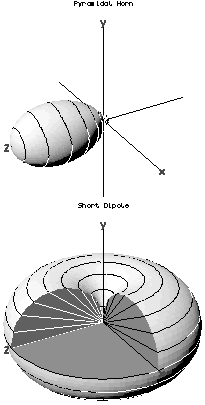
These axially symmetric antennas have radiation patterns with a similar symmetry, called omnidirectional patterns; they radiate equal power in all directions perpendicular to the antenna, with the power varying only with the angle to the axis, dropping off to zero on the antenna's axis.
This illustrates the general principle that if the shape of an antenna is symmetrical, its radiation pattern will have the same symmetry.
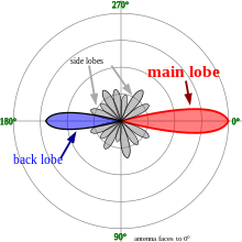
This results in minimum or zero radiation at certain angles where the radio waves from the different parts arrive out of phase, and local maxima of radiation at other angles where the radio waves arrive in phase.
Minor lobes usually represent radiation in undesired directions, so in directional antennas a design goal is usually to reduce the minor lobes.
Side lobe levels of −20 dB or greater are usually not desirable in many applications.
Attainment of a side lobe level smaller than −30 dB usually requires very careful design and construction.
Here, we present a common simple proof limited to the approximation of two antennas separated by a large distance compared to the size of the antenna, in a homogeneous medium.
Consequently, the amount of power transferred from the transmitter to the receiver can be expressed as the product of two independent factors; one depending on the directional properties of the transmitting antenna, and the other depending on the directional properties of the receiving antenna.
from the antenna (i.e. the power passing through unit area) is Here, the angles
Strictly, to include the mismatch, it should be called the realized gain,[4] but this is not common usage.
are directionally dependent properties of the transmitting and receiving antennas respectively.
Now for a given disposition of the antennas, the reciprocity theorem requires that the power transfer is equally effective in each direction, i.e. whence But the right hand side of this equation is fixed (because the orientation of antenna 2 is fixed), and so i.e. the directional dependence of the (receiving) effective aperture and the (transmitting) gain are identical (QED).
Analysis of a particular antenna (such as a Hertzian dipole), shows that this constant is
The power delivered to the receiver is therefore more usually written as (see link budget).
The effective aperture is however of interest for comparison with the actual physical size of the antenna.
This article incorporates public domain material from Federal Standard 1037C.