Bevel gear
Bevel gears are most often mounted on shafts that are 90 degrees apart, but can be designed to work at other angles as well.
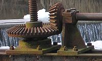
The most familiar kinds of bevel gears have pitch angles of less than 90 degrees and therefore are cone-shaped.
The use of a genuine bevel gear has even greater importance for the reliability of the axle than any other spare part.
[2] Mitre gears are useful for transmitting rotational motion at a 90-degree angle with a 1:1 ratio.
The cylindrical gear tooth profile corresponds to an involute (i.e. a triangle wave projected on the circumference of a circle), whereas the bevel gear tooth profile is an octoid[definition needed] (i.e. a triangle wave projected on the normal path of a circle of a sphere).
The other is the line or curve on which the tooth is set on the face of the gear: in other words the line or curve along which the cross-sectional profile is projected to form the actual three-dimensional shape of the tooth.
The primary effect of both the cross-sectional profile and the tooth line or curve is on the smoothness of operation of the gears.
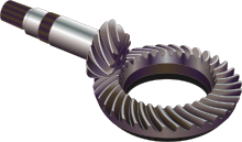
With straight bevel gears, the abrupt tooth engagement causes more noise, especially at high speeds, and impact stress on the teeth which makes them unable to take heavy loads at high speeds without breaking.
The bevel gear has many diverse applications such as locomotives, marine applications, automobiles, printing presses, cooling towers, power plants, steel plants, railway track inspection machines, etc.